

Vehicle driving device and vehicle driving method
- Summary
- Abstract
- Description
- Claims
- Application Information
AI Technical Summary
Benefits of technology
Problems solved by technology
Method used
Image

Examples
second embodiment
[0082]Referring to FIGS. 6A to 6F, a result of executing the fuel recovery control routine will be described. In this case, it is assumed that the fuel recovery is prohibited in a half of the cylinders in the step S4A.
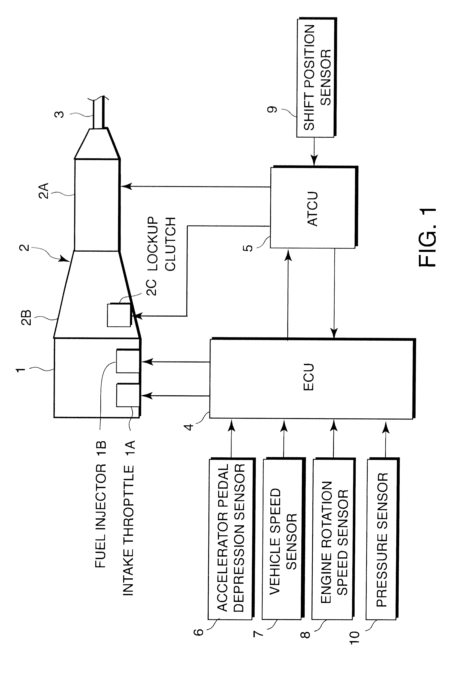
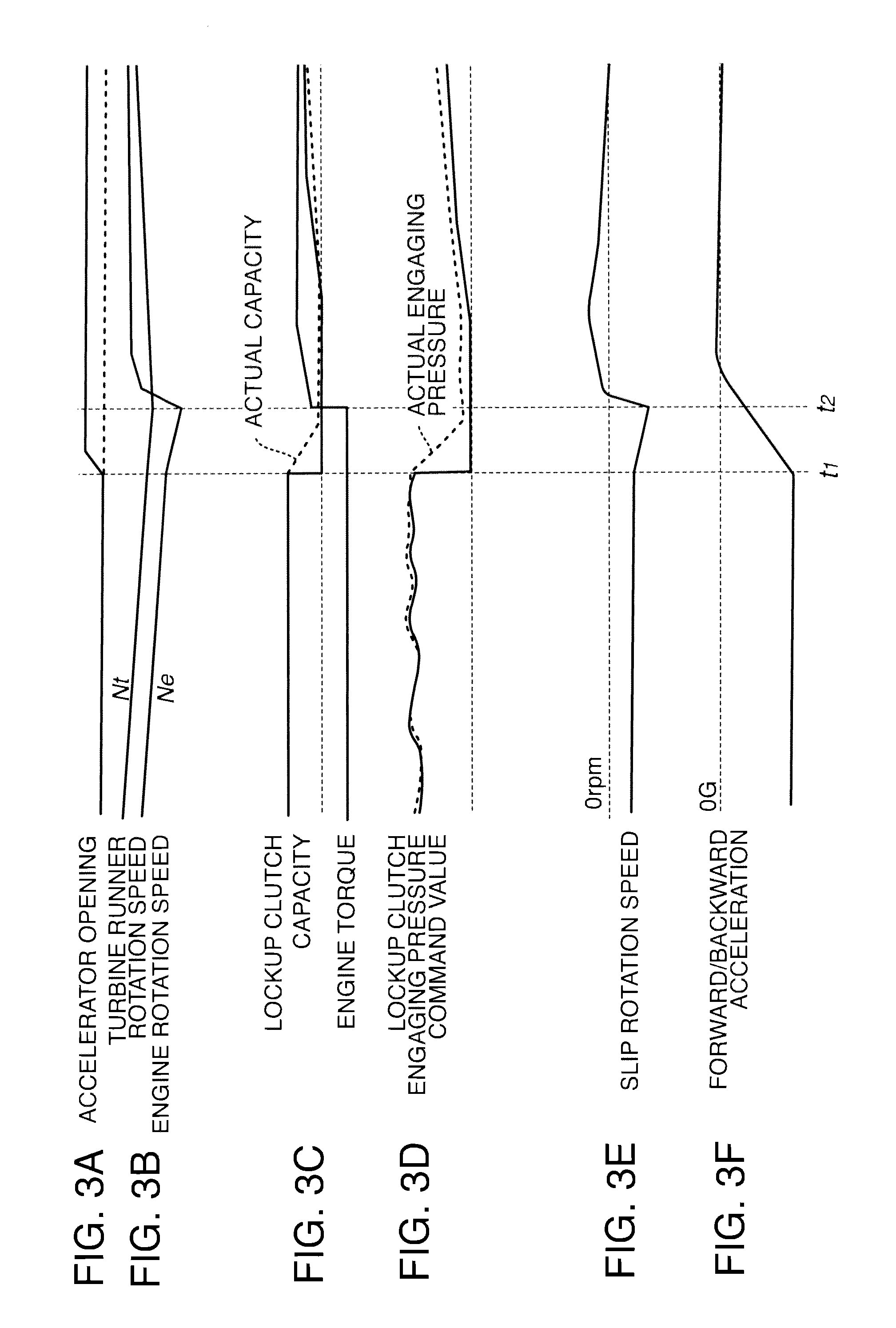
[0083]In this embodiment also, the conditions until the time t1 are identical to those of FIGS. 3A to 3F. As a driver slightly depresses the accelerator pedal at the time t1, the determination in the step S1 changes to be affirmative. As a result, in the step S2, the ECU 4 outputs a command value for decreasing the engaging pressure to the lockup clutch 2C via the ATCU 5 as illustrated in FIG. 6D. Due to a response delay of the hydraulic pressure, both the actual engaging pressure indicated by the dotted line in FIG. 6D and the lockup capacity indicated by the dotted line in FIG. 6C decrease gradually in contrast to a sudden decrease in the engaging pressure command value.
[0084]Meanwhile, since the determination in the step S3 becomes affirmative, the fuel recovery is...
third embodiment
[0092]Referring next to FIGS. 8A to 8F, a result of executing the fuel recovery control routine will be described.
[0093]With this fuel recovery control routine, both the fuel recovery and the increase in the opening rate of the intake throttle 1A are prohibited in overall cylinders during a recovery delay period until the time t2 after a driver slightly depresses the accelerator pedal at the time t1. As the recovery delay period is terminated at the time t2, the throttle opening increases as indicated by the dot-dashed line in FIG. 8A. If the intake air amount of the internal combustion engine 1 is suppressed to a low level during the recovery delay period, the output torque caused by the fuel recovery smoothly increases, as indicated by the dot-dashed line in FIG. 8C, even when the fuel recovery is immediately performed at the time 12, due to a response delay of the intake air amount against an increase in the accelerator opening. On the contrary, if the throttle opening increases...
first embodiment
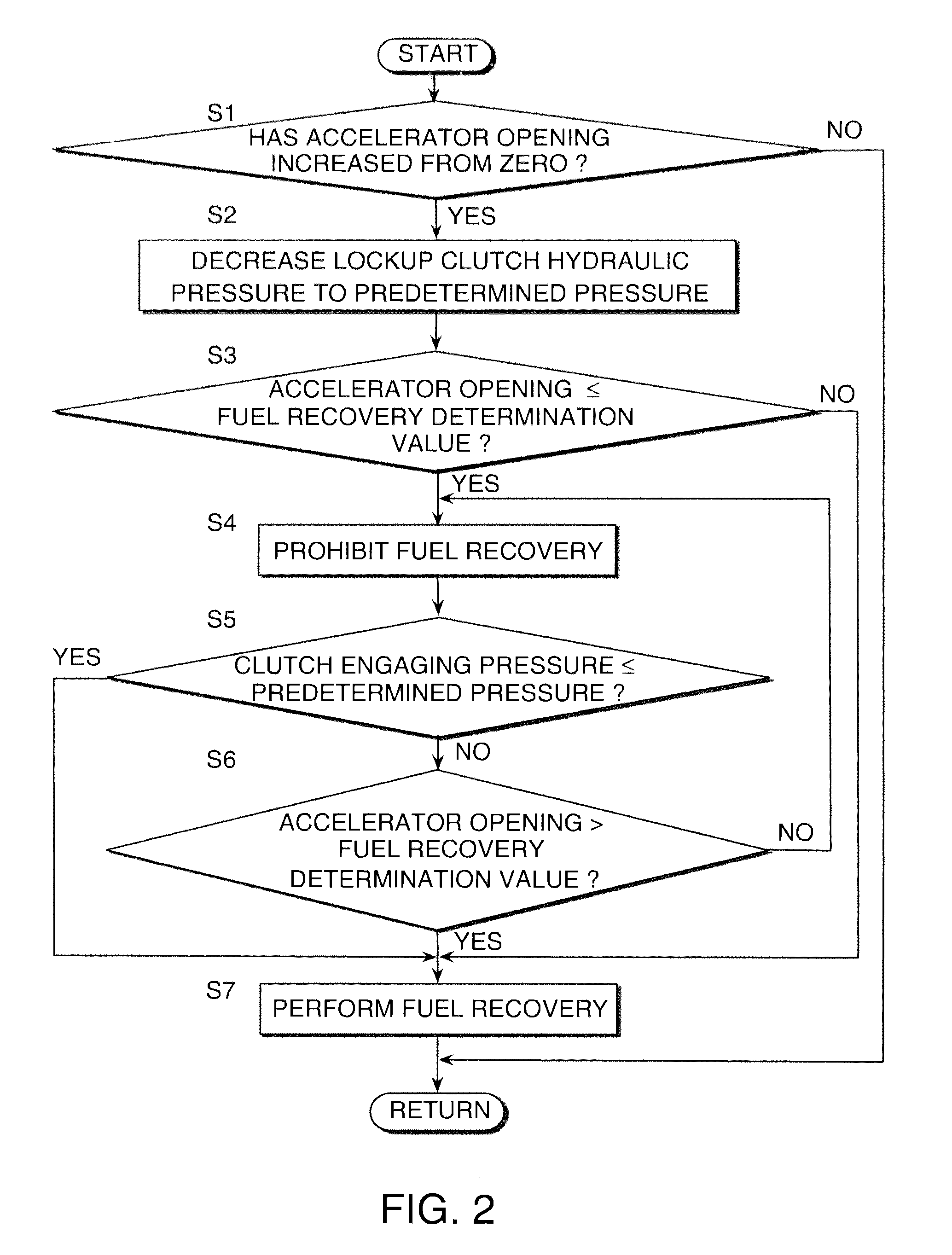
[0095]In this routine, the step S2 of the routine of FIG. 2 of the first embodiment is substituted with a step S2A. In addition, if the determination in the step S6 is negative, the processing is executed again not from the step S4, but from the step S2A.
[0096]In the step S2A, the ECU 4 applies an advance correction to the engaging pressure command value before it is output to the lockup clutch 2C. Specifically, by setting the engaging pressure command value to a value lower than the predetermined pressure, a decrease in the engaging pressure of the lockup clutch 2C is accelerated. In addition, the ECU 4 performs feedback control of the engaging pressure by repeatedly processing the steps S2A to S6 such that the engaging pressure of the lockup clutch 2C finally converges to the predetermined pressure. As a result, the processing of the step S2A is repeatedly executed from the time t1 at which the accelerator pedal is depressed to the time t2 at which the engaging pressure of the loc...
PUM
 Abstract
Description
Claims
Application Information