Method for manufacturing fluorescent powder substrate and liquid crystal module using fluorescent powder substrate

Active Publication Date: 2014-01-02
TCL CHINA STAR OPTOELECTRONICS TECH CO LTD
View PDF9 Cites 4 Cited by
  • Summary
  • Abstract
  • Description
  • Claims
  • Application Information

AI Technical Summary

Benefits of technology

[0006]An object of the present invention is to provide a method for manufacturing a fluorescent powder substrate, which has a simple process and the fluorescent powder substrate so manufactured, when assembled wit

Problems solved by technology

In such a structure, the LED chip and the epoxy resin and the silica are set in tight engagement with each other, whereby heat dissipation from the LED chip is inefficient.
However, epoxy resin is poor in resisting high temperature and being long set in a high t

Method used


Image

  • Method for manufacturing fluorescent powder substrate and liquid crystal module using fluorescent powder substrate
  • Method for manufacturing fluorescent powder substrate and liquid crystal module using fluorescent powder substrate
  • Method for manufacturing fluorescent powder substrate and liquid crystal module using fluorescent powder substrate

Examples


Embodiment Construction

[0047]To further expound the technical solution adopted in the present invention and the advantages thereof, a detailed description is given to a preferred embodiment of the present invention and the attached drawings.

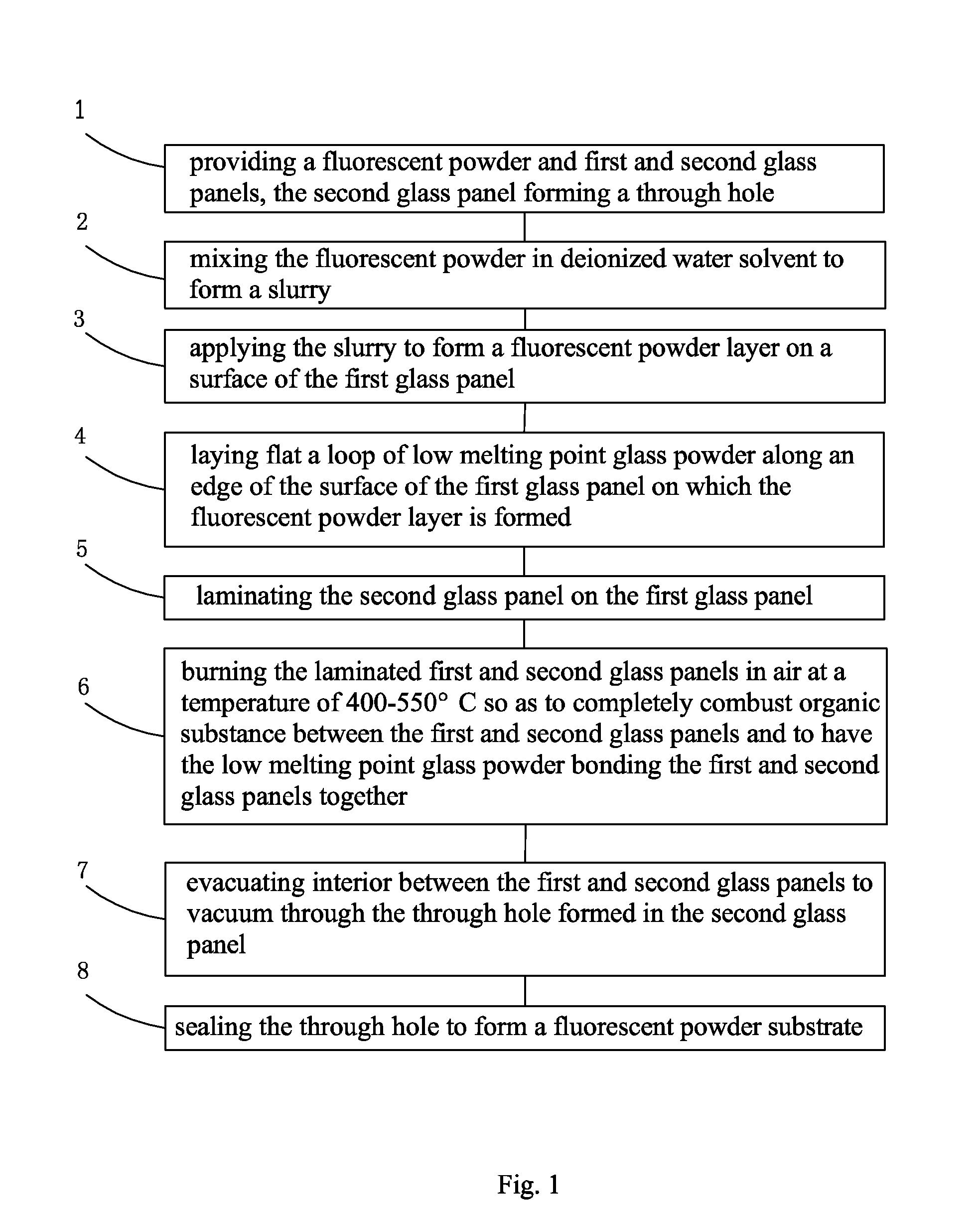
[0048]Referring to FIG. 1, the present invention provides a method for manufacturing a fluorescent powder substrate, which comprises the following steps:

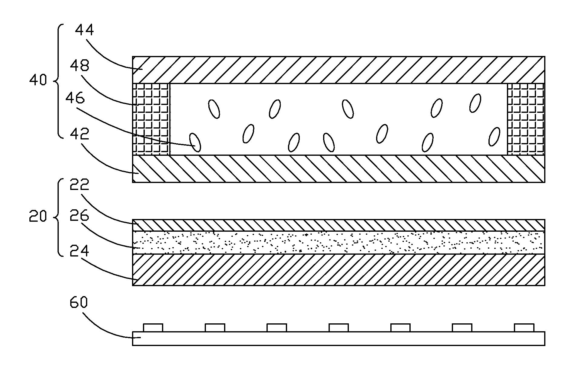
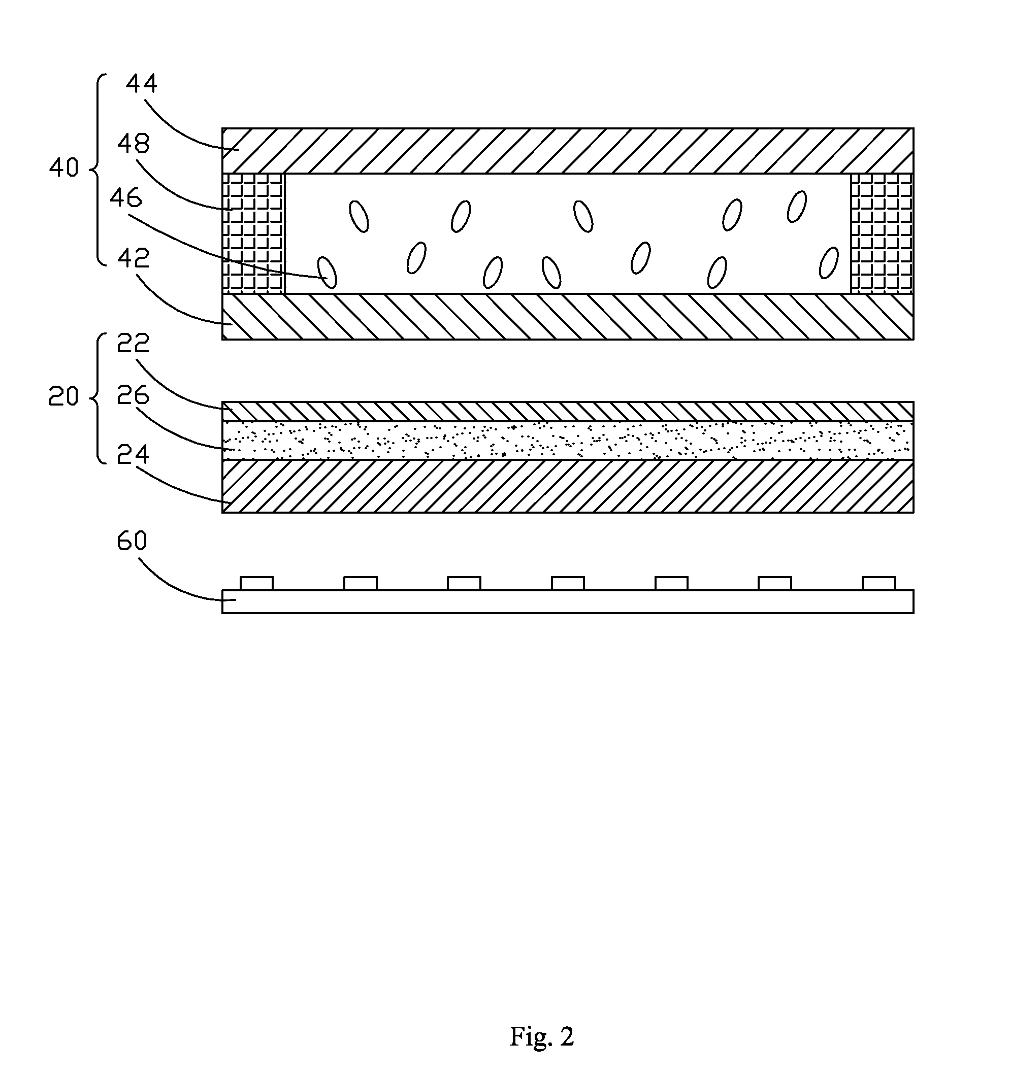
[0049]Step 1: providing a fluorescent powder and first and second glass panels, the second glass panel forming a through hole.

[0050]The fluorescent powder is formed by mixing oxides, silicates, aluminates, nitrides, and oxynitrides. The specific composition can be determined according to the color of the light emitting from a light-emitting chip used and the color of light obtained when the color of the light transmits through the fluorescent powder. The first and second glass panels are both high transmittance glass and the second glass panel forms a through hole, which has a hole diameter of 0.2-1 cm.

[0051]Step 2: mi...


PUM

PropertyMeasurementUnit
Temperatureaaaaaaaaaa
Diameteraaaaaaaaaa
Sizeaaaaaaaaaa

Abstract

A method for manufacturing fluorescent powder substrate includes (1) providing a fluorescent powder and glass panels of which one forms a through hole; (2) mixing the fluorescent powder in deionized water solvent to form a slurry; (3) applying the slurry to form a fluorescent powder layer on one glass panel; (4) laying flat a loop of low melting point glass powder on the glass panel on which the fluorescent powder layer is formed; (5) laminating the other glass panel on the glass panel; (6) burning the laminated glass panels at a temperature of 400-550° C. to completely combust organic substance therebetween and to have the low melting point glass powder bonding the glass panels together; (7) evacuating interior between the glass panels through the through hole; and (8) sealing the through hole to form a fluorescent powder substrate.

Description

BACKGROUND OF THE INVENTION[0001]1. Field of the Invention[0002]The present invention relates to the field of liquid crystal displaying, and in particular to a method for manufacturing a fluorescent powder substrate and a liquid crystal module ufsing the fluorescent powder substrate.[0003]2. The Related Arts[0004]Liquid crystal display (LCD) has a variety of advantages, such as thin device body, low power consumption, and being free of radiation, and is thus widely used. Most of the LCDs that are currently available in the market are backlighting LCDs, which comprise a liquid crystal panel and a backlight module. The operation principle of the liquid crystal panel is that liquid crystal molecules are interposed between two parallel glass substrates and a plurality of vertical and horizontal fine electrical wires is arranged between the two glass substrates, whereby the liquid crystal molecules are controlled to change direction by application of electricity in order to refract light...

Claims


Application Information

Patent Timeline
IPC IPC(8): G02F1/13357B32B37/14B32B37/02
CPCG02F1/133617H05B33/10G02F1/1336B32B17/10009B32B17/10146B32B17/10807B32B17/10944G02F1/133614G02F1/133602C03C27/00
Inventor WANG, YEWEN
Owner TCL CHINA STAR OPTOELECTRONICS TECH CO LTD
Why Eureka
Try Eureka