
Medical cart system

a medical cart and cart system technology, applied in the field of remote medical care, can solve the problems of inability to provide individualized care to patients and/or insurance programs, inability to meet patient needs, etc., and achieve the effect of satisfying patient experien

Inactive Publication Date: 2015-10-22
HUNTINGDON TELEMED
View PDF1 Cites 15 Cited by
  • Summary
  • Abstract
  • Description
  • Claims
  • Application Information

AI Technical Summary

Benefits of technology

This patent describes a medical cart that allows for a doctor and patient to have a similar experience when in the same location. The cart has a facilitator to ensure a satisfactory experience for the patient. The cart is easy to transport, reconfigurable, and can be used by a single doctor or medical practitioner to provide care to multiple patients at multiple facilities. The main benefits of this invention are improved doctor-patient interactions and increased flexibility and accessibility of medical care.

Problems solved by technology

In some cases, access to medical care for certain specialties such as, for example, psychological care may not be widely available particularly in rural areas or even urban areas that are significantly spread out.
In other cases, care may be available, but the cost of providing individualized care may be prohibitive to patients and / or insurance programs.
In prior art systems, however, the doctor / patient interaction facilitated by the systems may be less than optimal.
Conventional remote care systems do not provide that.
Moreover, because of their construction, weight, power structure, etc., prior art remote care systems were effectively bound to a single medical facility and were not effectively and easily transported from one facility to another facility.
The cost of remote care systems that are effectively bound to a single medical facility may be prohibitive because multiple systems would be needed to service multiple facilities, which increases costs and reduces availability of care.

Method used


Image

  • Medical cart system
  • Medical cart system
  • Medical cart system

Examples


Embodiment Construction

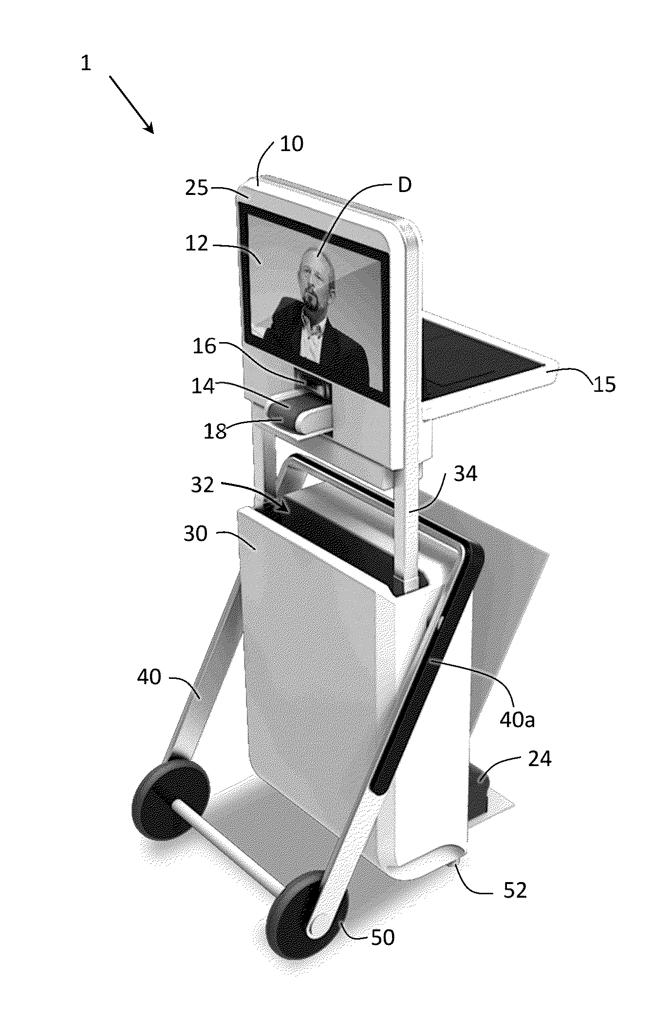
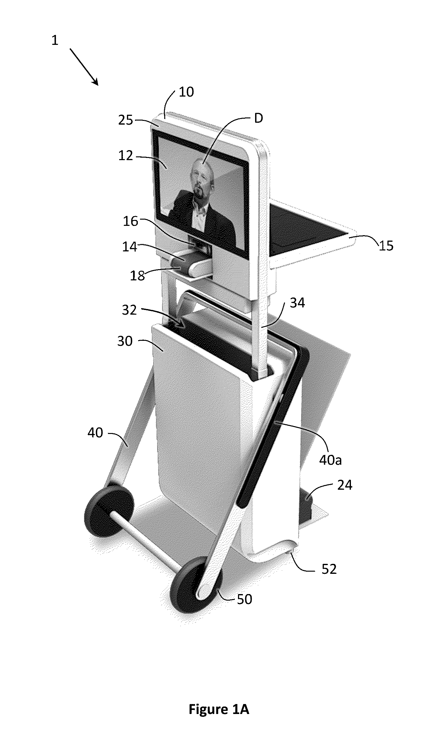
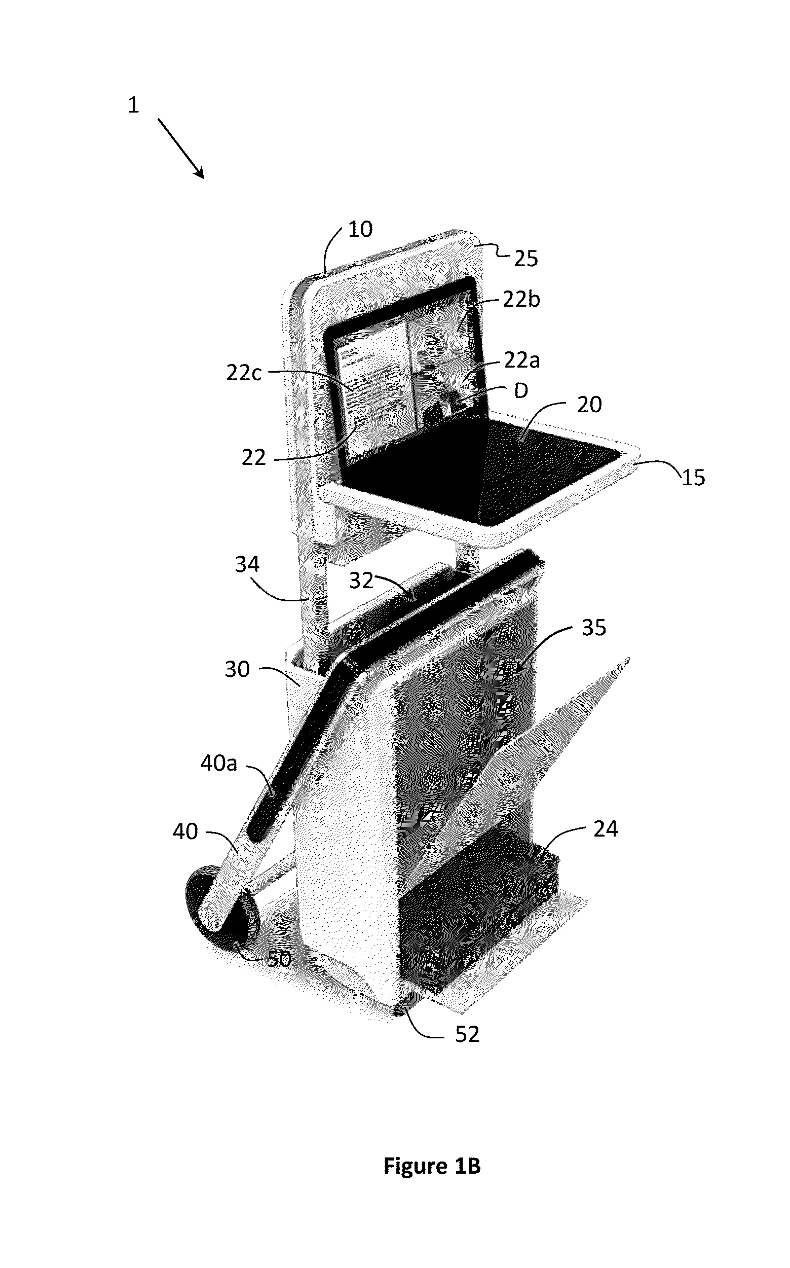
[0020]FIGS. 1A and 1B illustrate an exemplary medical cart 1. FIG. 1A illustrates the exemplary medical cart 1 from the perspective of a patient while FIG. 1B illustrates the cart 1 from the perspective of a facilitator as described below.

[0021]The medical cart 1 includes an interface assembly 10.

[0022]On the patient side (FIG. 1A), the interface assembly 10 includes a patient-side display 12, a speaker 14, a camera 16 and a microphone 18. The cart 1 is also equipped with a communication module as further disclosed below that receives video and audio communication from a location remote to the location of the cart 1. The communication module displays the received video on the display 12 and plays the received audio through the speaker 14. The communication module also receives a video image from the camera 16 and sound from the microphone 18, and transmits the received video image and sound to the remote location. The communication module may be implemented as a node in a wired or w...


PUM


Abstract

A medical cart includes an interface assembly including a display, a speaker, a camera and a microphone. The interface assembly is operatively connected to an enclosure at a connecting portion that is operable to reposition the interface assembly from a transporting configuration in which the interface assembly is disposed inside the enclosure to a deployed configuration in which the interface assembly is disposed outside of the enclosure. The medical cart also includes a set of wheels operably connected to at least one of the enclosure or a pivoting assembly operable to pivot from the transporting configuration in which only the set of wheels makes contact with a transporting surface to the deployed configuration in which a portion of the cart in addition to the set of wheels makes contact with the transporting surface for stabilizing the cart in the deployed configuration.

Description

FIELD OF THE INVENTION[0001]The present disclosure relates generally to remote medical care and particularly to a medical cart system.BACKGROUND[0002]In some cases, access to medical care for certain specialties such as, for example, psychological care may not be widely available particularly in rural areas or even urban areas that are significantly spread out. In other cases, care may be available, but the cost of providing individualized care may be prohibitive to patients and / or insurance programs.[0003]Remote care systems have been proposed in which a doctor or other medical practitioner may provide some level of care from a location remote to the patient. In prior art systems, however, the doctor / patient interaction facilitated by the systems may be less than optimal. Remote care systems should allow the patient to experience interaction with the doctor that is as similar as possible to the interaction that the patient would have experienced if the patient and the doctor were i...

Claims


Application Information

Patent Timeline
IPC IPC(8): H04W80/04B62B1/26B62B1/20G16H40/67
CPCH04W80/04B62B1/26B62B1/208B62B3/02B62B5/067B62B2202/56G16H40/67B62B1/12G06F1/1605
Inventor UTTLEY, THOMASBOLL, DAVIDPAYUMO, MAYNARDRABBITT, WILLIAMSZPAK, JAMESTILK, JASONVYSTRCIL, ROBERT
Owner HUNTINGDON TELEMED
Learn More