Soil Spreading Scraper Device

a scraper device and soil technology, applied in soil-working equipment, shovels, ploughs, etc., can solve the problems of wear of the impeller blade on the spinning disc, difficulty in manufacturing the impeller blade with the degree of precision required for optimal efficiency, and inability to readily permit maintenance as required. , to achieve the effect of optimizing the efficiency of the impeller

Active Publication Date: 2015-10-29
ELMERS WELDING & MFG LTD
View PDF0 Cites 3 Cited by
  • Summary
  • Abstract
  • Description
  • Claims
  • Application Information

AI Technical Summary

Benefits of technology

[0038]The radial adjustability of a wear member which projects radially outwardly beyond the end of the impeller blade readily permits the outer end of the wear member to be closely located relative to the surrounding peripheral edge of the chamber receiving the impeller blade therein for optimal efficiency of operation of the impeller using a simple construction.

Problems solved by technology

Many of the ditcher implements noted above encounter problems of wear of the impeller blades on the spinning discs thereof.
The impeller blades and the liners supported thereon must be rotated in close proximity to a peripheral wall of the chamber rotatably receiving the impeller blades therein for efficient operation, however, it can be difficult to manufacture the impeller blades with the degree of precision required for optimal efficiency.
Among the ditcher type implements noted above which include a kicker above the cutting blade, another problem which is encountered is the lodging of debris between the kicker and the cutting blade which prevents continued rotation of the kicker.
Examples of reverser mechanisms for various implements are disclosed in U.S. Pat. No. 7,669,400 by Naaktgeboren, U.S. Pat. No. 6,681,552 by Nelson et al, and U.S. Pat. No. 3,608,557 by Evans; however, none of the prior art devices are suitably arranged for incorporation into a ditcher implement in a manner which readily permits maintenance as required.

Method used


Image

  • Soil Spreading Scraper Device
  • Soil Spreading Scraper Device
  • Soil Spreading Scraper Device

Examples


first embodiment

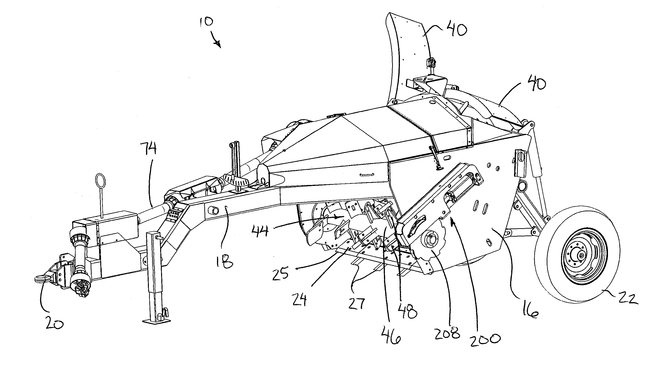
[0104]In the first embodiment, the kicker blades 48 are arranged such that a total of 16 blades are provided in four rows. Each row includes four axially spaced apart kicker blades 48 which extend in a common radial direction of the shaft 46. The four rows are angularly offset in the circumferential direction at 90 degree intervals from one another. The soil striking sequence of the kicker thus involves four kicker blades 48 striking the cut soil at axially spaced apart positions at each 90 degree interval of rotation of the kicker shaft.

second embodiment

[0105]In FIGS. 17 to 19, a total of eight kicker blades are provided at evenly spaced apart positions in the axial direction of the kicker shaft. Each kicker blade is angularly offset in the circumferential direction relative to all other ones of the kicker blades such that a single kicker blade is provided at each 45 degree interval about the circumference of the kicker shaft. The resulting soil striking sequence of the kicker blades prescribed by the mounting arrangement of the kicker blades on the shaft thus involves a single kicker blade striking the cut soil with each 45 degree interval of rotation of the kicker shaft. The striking of the kicker blades occurs at evenly spaced positions throughout the rotation. The prescribed ground striking sequence is further arranged such that no two kicker blades which are adjacent one another in the axial direction will strike the soil immediately one after the other, or adjacent to one another in the overall order of the prescribed soil st...


PUM


Abstract

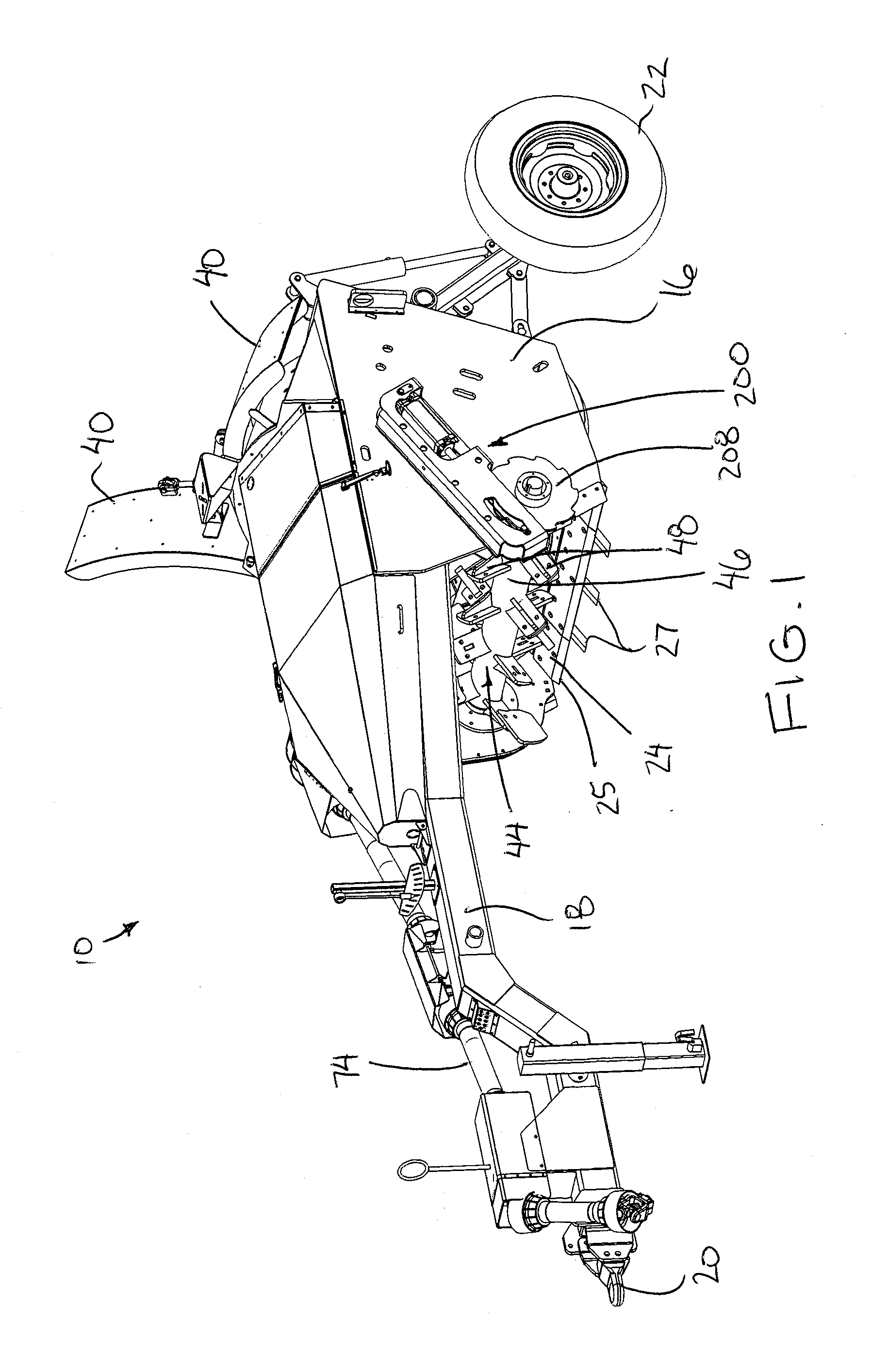
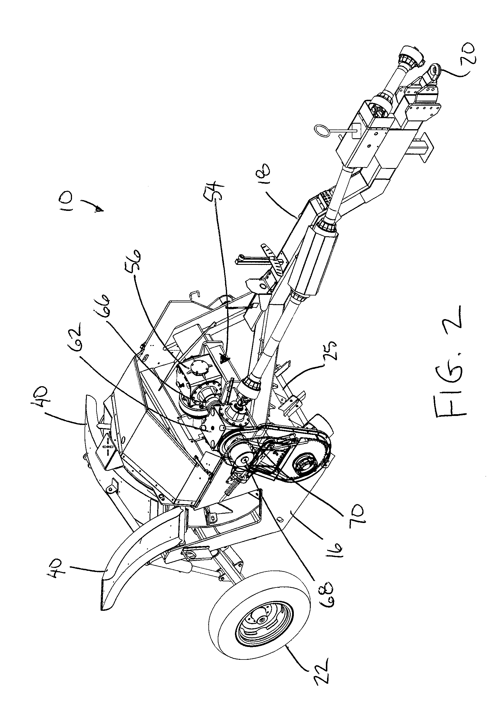
A soil spreading scraper device comprises a cutting blade for cutting a top layer of soil from the ground, a kicker for throwing the cut soil rearward from the cutting blade, and an impeller member rotatable within a plane of rotation extending upward and rearward from the cutting blade for capturing the soil thrown by the kicker and spreading the cut soil generally radially outward relative to an axis of rotation of the impeller.

Description

FIELD OF THE INVENTION[0001]The present invention relates to a soil spreading scraper device which is arranged to cut a top layer of soil from the ground as the device is displaced along the ground in a forward working direction and which is arranged to spread the cut soil transversely to the forward working direction.BACKGROUND[0002]In some situations it is required to pick up soil at one location and transport it to another. In the case of road building for instance, the contour of the ground is changed to form a road by taking the soil from one location and placing it in another. Not only must the soil be removed from one location, it must also be placed in another specific location.[0003]In many situations however, it is only desired to remove the soil from its current location, and the location it is moved to is not critical. Often it is desired to simply spread the removed soil so that it does not interfere with future operations on the land. An example is where ditches are ma...

Claims


Application Information

Patent Timeline
Patent Type & Authority Applications(United States)
IPC IPC(8): A01B49/02A01B39/08A01B39/04
CPCA01B49/022A01B39/085A01B39/04A01B37/00
Inventor THOMPSON, MARK C.
Owner ELMERS WELDING & MFG LTD
Why Eureka
Try Eureka