Attachment of a discharge conduit of a turbine engine

a turbine engine and discharge conduit technology, applied in liquid fuel engines, combustion air/fuel air treatment, machines/engines, etc., can solve the problems of inability to screw the discharge conduits to the intermediate casing, disadvantageous engine assembly and maintenance, etc., and achieve the effect of simple, effective and economical

Active Publication Date: 2015-10-29
SN DETUDE & DE CONSTR DE MOTEURS DAVIATION S N E C M A
View PDF3 Cites 11 Cited by
  • Summary
  • Abstract
  • Description
  • Claims
  • Application Information

AI Technical Summary

Benefits of technology

[0011]The invention thus makes it easier to mount the discharge conduit, it being possible for a single operator to produce the resilient snap-in attachment without a particular tool necessarily being required. The invention may thus also be adapted to turbine engines in which the environment around the discharge conduits is of a restricted size.
[0019]Advantageously, the opening in the intermediate casing has a peripheral edge having a lead-in chamfer at the downstream end and a lead-out chamfer at the upstream end in order to make it easier to mount and dismount the conduit, respectively.
[0025]Pre-mounting the discharge conduit makes it easier to mount, and this can be carried out by one person. In the pre-mounting position, the conduit can bear against the intermediate casing, which holds it in this position (in a cantilevered manner). The movement of the conduit from this pre-mounting position into a different position is particularly advantageous since it makes it possible to limit or even eliminate any direct contact between the conduit and the casing. It also allows the assembly of parts not to be over-stressed and prevents hyperstatic problems. The peripheral seal ensures that the conduit is sealed by limiting or even eliminating the air escaping in the region of its intake end.

Problems solved by technology

However, this attachment technology cannot always be used.
In certain turbine engines, owing to the equipment in the engine compartment and the shape of the discharge conduits, it is not possible to screw the conduits to the intermediate casing.
This constraint is disadvantageous for assembly and maintenance of the engine since it is necessary to mount the conduits and the collars in the same operation.
Since the environment is of a very restricted size and the number of operators is limited (especially during maintenance and owing to the size), the current solution is hardly conceivable for the service life of the engine.

Method used


Image

  • Attachment of a discharge conduit of a turbine engine
  • Attachment of a discharge conduit of a turbine engine
  • Attachment of a discharge conduit of a turbine engine

Examples


Embodiment Construction

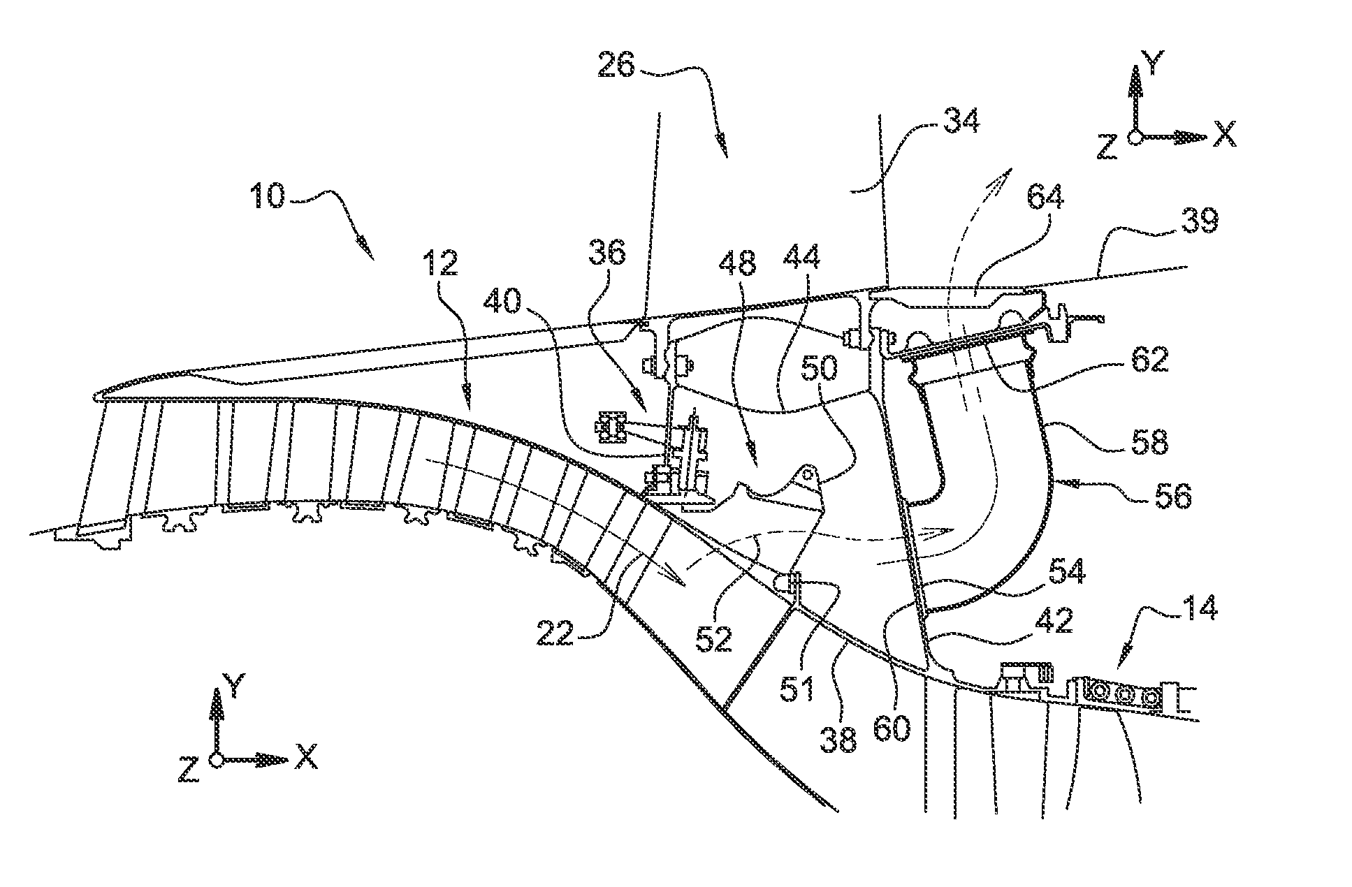
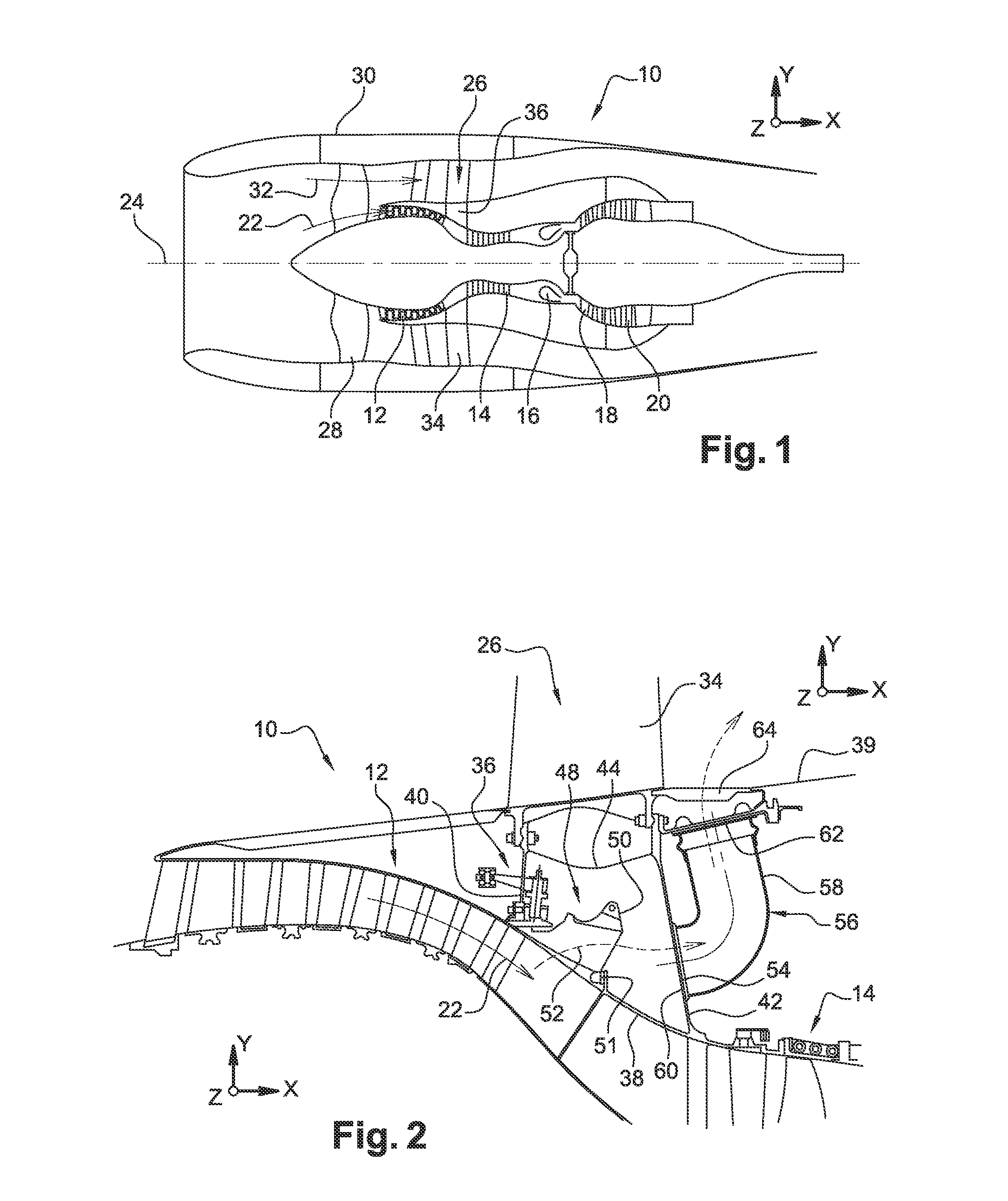
[0033]As shown in FIG. 1, which is a schematic axial section through a bypass turbine engine 10, such a turbojet engine generally comprises, from upstream to downstream in the direction of flow of the gases, a low-pressure compressor 12, a high-pressure compressor 14, a combustion chamber 16, a high-pressure turbine 18 and a low-pressure turbine 20, which define a flow duct for a primary gas flow 22.

[0034]The high-pressure turbine 18 is rigidly connected to the high-pressure compressor 14 so as to form a high-pressure body, while the low-pressure turbine 20 is rigidly connected to the low-pressure compressor 12 so as to form a low-pressure body, such that each turbine drives the associated compressor in rotation about a turbojet-engine shaft 24 under the effect of the thrust of the gases coming from the combustion chamber 16.

[0035]An intermediate casing 26 is conventionally interposed between the low-pressure compressor 12 and the high-pressure compressor 14.

[0036]In the case of byp...


PUM

PropertyMeasurementUnit
angleaaaaaaaaaa
angleaaaaaaaaaa
resilientaaaaaaaaaa

Abstract

Discharge conduit for a turbine engine, comprising an air intake end, an air outlet end and a tubular sleeve for guiding air between said ends, said air intake end being equipped with means for attachment to an intermediate casing of the turbine engine, characterized in that said attachment means are of the resilient snap-in type.

Description

TECHNICAL FIELD[0001]The present invention relates to a discharge conduit for a turbine engine, and more particularly to the attachment of such a conduit.PRIOR ART[0002]A bypass turbine engine comprises a flow duct for a primary flow or hot flow and a flow duct for a secondary flow or cold flow. It is known to equip such a turbine engine with discharge valves, which are sometimes referred to as variable bleed valves (VBV).[0003]Valves of this type are intended to regulate the air intake flow rate in the primary duct, in particular in order to limit the risk of a surge in the compressor of the turbine engine by making it possible to carry away or discharge an air flow in the secondary duct. In addition, if the primary duct is accidentally penetrated by water, in particular in the form of rain or hail, or various types of debris which are likely to adversely affect the operation of the turbine engine, these valves make it possible to collect this water or debris which is carried outwa...

Claims


Application Information

Patent Timeline
Patent Type & Authority Applications(United States)
IPC IPC(8): F01D25/24F02C7/04
CPCF02C7/04F01D25/24F01D9/02F02C9/18F04D29/545F04D29/644F04D27/0207
Inventor LACROIX, FLORIAN BENJAMIN KEGOUPIL, FREDERIC JACQUES EUGENEROBIN, NOEL JOSEPH CAMILLEVITRA, JULIEN
Owner SN DETUDE & DE CONSTR DE MOTEURS DAVIATION S N E C M A
Why Eureka
Try Eureka