Valve, Valve Device and Method for Assembling a Valve Device

Inactive Publication Date: 2015-10-29
KNORR-BREMSE SYST FUER NUTZFAHRZEUGE GMBH
View PDF6 Cites 0 Cited by
  • Summary
  • Abstract
  • Description
  • Claims
  • Application Information

AI Technical Summary

Benefits of technology

[0019]In this case, the circular profile section and the tetragonal profile section of the receiving section may extend through the driver as a common passage opening along a receiving axis of the actuation lever in the receiving section. In this case, the circular profile section and the tetragonal profile section of the receiving section may have a common central axis of longitudinal extent through the driver. Such an embodiment offers the advantage that a space-saving receptacle for an actuation lever with a, for example, circular cross-sectional profile or tetragonal cross-sectional profile is provided.
[0020]In particular, the receiving section may be designed to engage in U-shape fashion around narrow sides of a tetragonal cross-sectional profile of an actuation lever with a tetragonal cross-sectional profile. In this case, the receiving section can be placed in contact with the narrow sides of the tetragonal cross-sectional profile and with subsections, adjoining the narrow sides, of long sides of the tetragonal cross-sectional profile. The receiving section may also be designed such that, to fasten an actuation lever with a tetragonal cross-sectional profile, said receiving section engages with firm clamping action around the narrow sides of the actuation lever. A narrow side may be understood to mean a side of the actuation lever which has a smaller width than at least one other side of the actuation lever. In this case, the receiving section may be designed to make mechanical contact with subsections, adjoining the narrow sides, of long sides of the actuation lever with a tetragonal cross-sectional profile. Instead of the actuation lever being fixed only at its main surfaces, the actuation lever is engaged around and/or clamped at the narrow sides, such that the actuation lever with the tetragonal cross-sectional profile can be easily inserted into the receiving section and, if necessary, easily displaced in the receiving section relative to the driver.
[0021]Furthermore, the receiving section may be designed such that it can be placed in contact with two circumferential subsections of a circular cross-sectional profile of an actuation lever with a circular cross-sectional profile. Here, the receiving section is designed such that it can be placed in abutment against the circular cross-sectional profile of the actuation lever with circular cross-sectional profile over a part of the circumference. In particular, the receiving section may be designed such that it can be placed in contact with a first

Problems solved by technology

Often, however, a valve of this type is intended for use in a variety of environments

Method used


Image

  • Valve, Valve Device and Method for Assembling a Valve Device
  • Valve, Valve Device and Method for Assembling a Valve Device
  • Valve, Valve Device and Method for Assembling a Valve Device

Examples


Example

DETAILED DESCRIPTION OF THE DRAWINGS

[0033]In the following description of the preferred exemplary embodiments of the present invention, the same or similar reference signs will be used to denote elements of similar action illustrated in the various drawings, wherein a repeated description of such elements will be omitted.

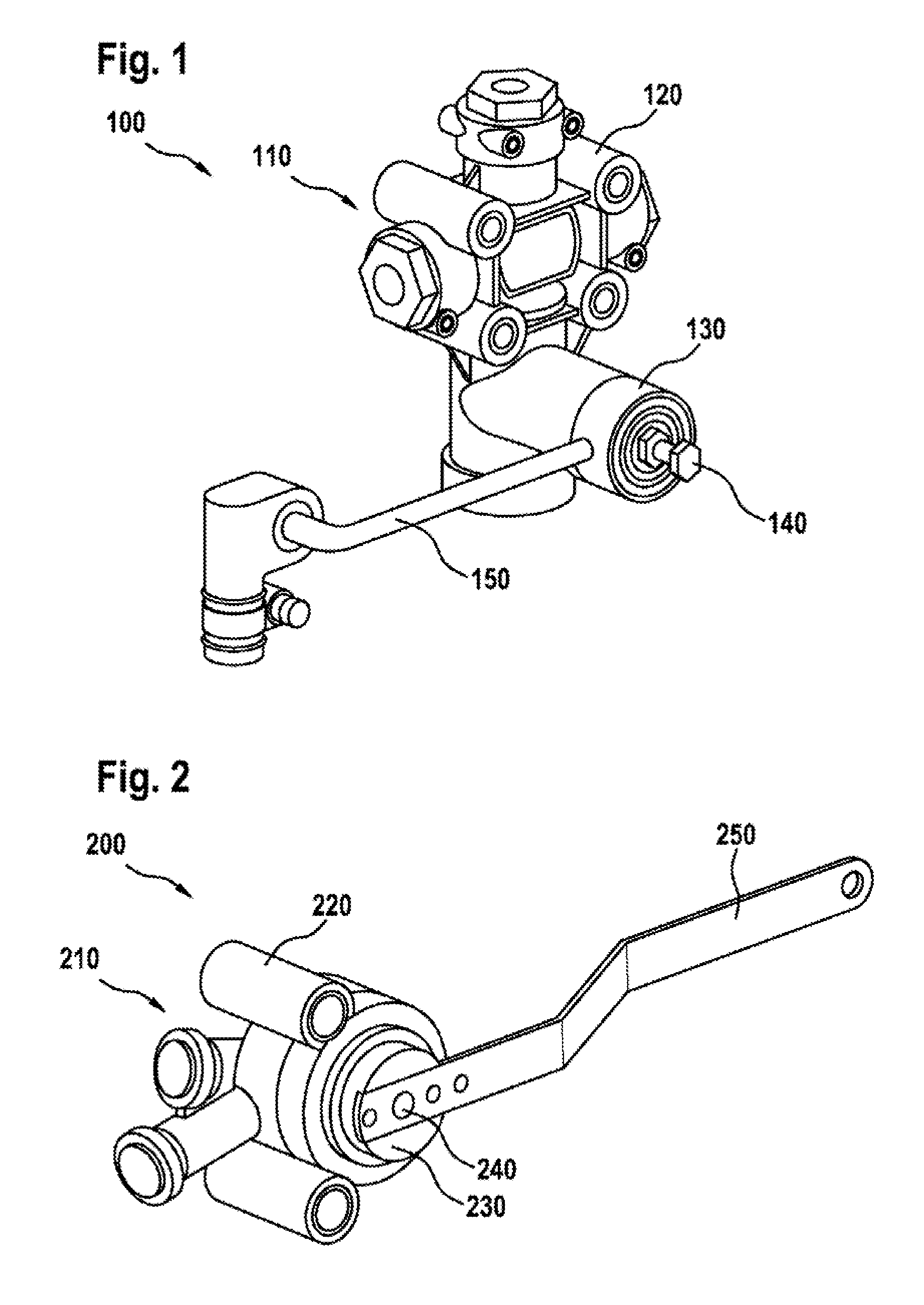
[0034]FIG. 1 is a perspective illustration of a valve device 100. The valve device 100 has a valve 110 with a valve body 120 and with a driver 130. Furthermore, the valve device 100 has a fastening device 140 and an actuation lever 150. The actuation lever 150 is attached to the driver 130 of the valve 110 by way of the fastening device 140. The actuation lever 150 has a circular cross-sectional profile. The driver 130 and the fastening device 140 are designed specifically for attachment of the actuation lever 150 with the circular cross-sectional profile as shown in FIG. 1.

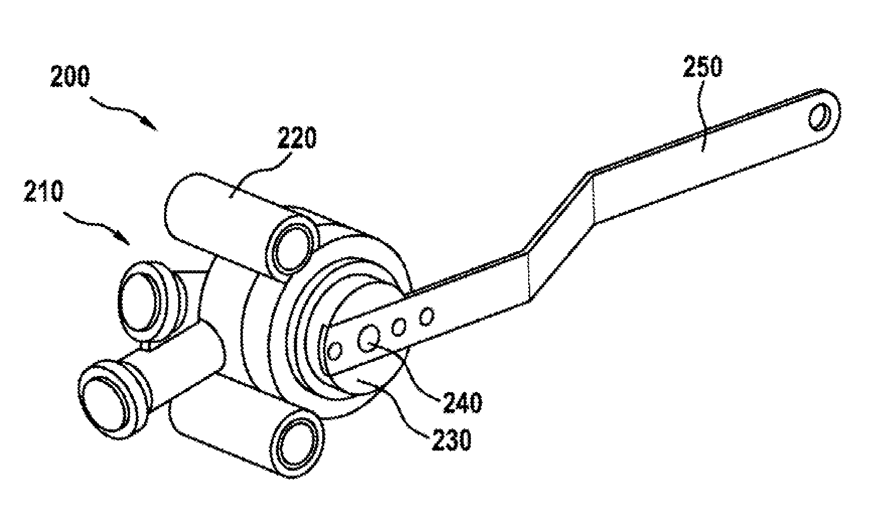
[0035]FIG. 2 is a perspective illustration of a valve device 200. The valve device 200 has a ...


PUM


Abstract

A valve, in particular a pneumatic suspension valve for a vehicle, is provided. The valve includes a valve body with a driver. The driver has a receiving section for receiving an actuating lever which can be fixed on the driver. Said receiving section is design to receive, without retrofitting the receiving section, an actuating lever having a first cross-sectional profile to receive an actuating lever having a second cross-sectional profile which is different from the first cross-sectional profile.

Description

CROSS REFERENCE TO RELATED APPLICATIONS[0001]This application is a continuation of PCT International Application No. PCT / EP2014 / 050303, filed Jan. 9, 2014, which claims priority under 35 U.S.C. §119 from German Patent Application No. 10 2013 100 247.1, filed Jan. 11, 2013, the entire disclosures of which are herein expressly incorporated by reference.BACKGROUND AND SUMMARY OF THE INVENTION[0002]The present invention relates to a valve, in particular a pneumatic suspension valve for a vehicle, to a valve device and to a method for assembling a valve device.[0003]It is commonly the case that a valve can be actuated by way of an actuation lever. An actuation lever may be mounted on a driver of the valve. In this case, the driver serves for transmitting movement between the actuation lever and valve. Often, however, a valve of this type is intended for use in a variety of environments, which necessitates expensive, specific conversion for the respective usage scenario.[0004]It is the ob...

Claims


Application Information

Patent Timeline
IPC IPC(8): F16K31/60
CPCF16K31/602F16K31/607F16F9/46F16K27/06F16K31/60G05G1/04
Inventor KONCZ, LASZLOFARKAS, GABORPAPP, LAJOSMAJLATH, ATTILA
Owner KNORR-BREMSE SYST FUER NUTZFAHRZEUGE GMBH
Why Eureka
Try Eureka