
Display device and method of driving the same

Active Publication Date: 2015-10-29
LG DISPLAY CO LTD
View PDF0 Cites 41 Cited by
  • Summary
  • Abstract
  • Description
  • Claims
  • Application Information

AI Technical Summary

Benefits of technology

The present invention provides a display device and method of driving it that can analyze a plurality of touch sensing signals sequentially received from a plurality of touch groups arranged along a plurality of gate lines to determine a touch event on a panel during a plurality of touch sensing periods provided in one frame period. This allows for more efficient and accurate touch sensing, and better user experience. The display device includes a panel with a plurality of touch groups having a plurality of self-capacitance electrodes arranged along a plurality of gate lines, a touch sensing unit, a data driver, a gate driver, and a timing controller. The method includes sequentially supplying a scan pulse to a plurality of gate lines, supplying a common voltage to a plurality of touch groups, and displaying an image on a plurality of pixels corresponding to the plurality of gate lines. This technology can improve touch sensing capabilities and provide better user experience for display devices.

Problems solved by technology

That is, an electric field is generated between the pixel electrode and the common electrode to derive the liquid crystal for displaying an image may cause unwanted noise for the touch.
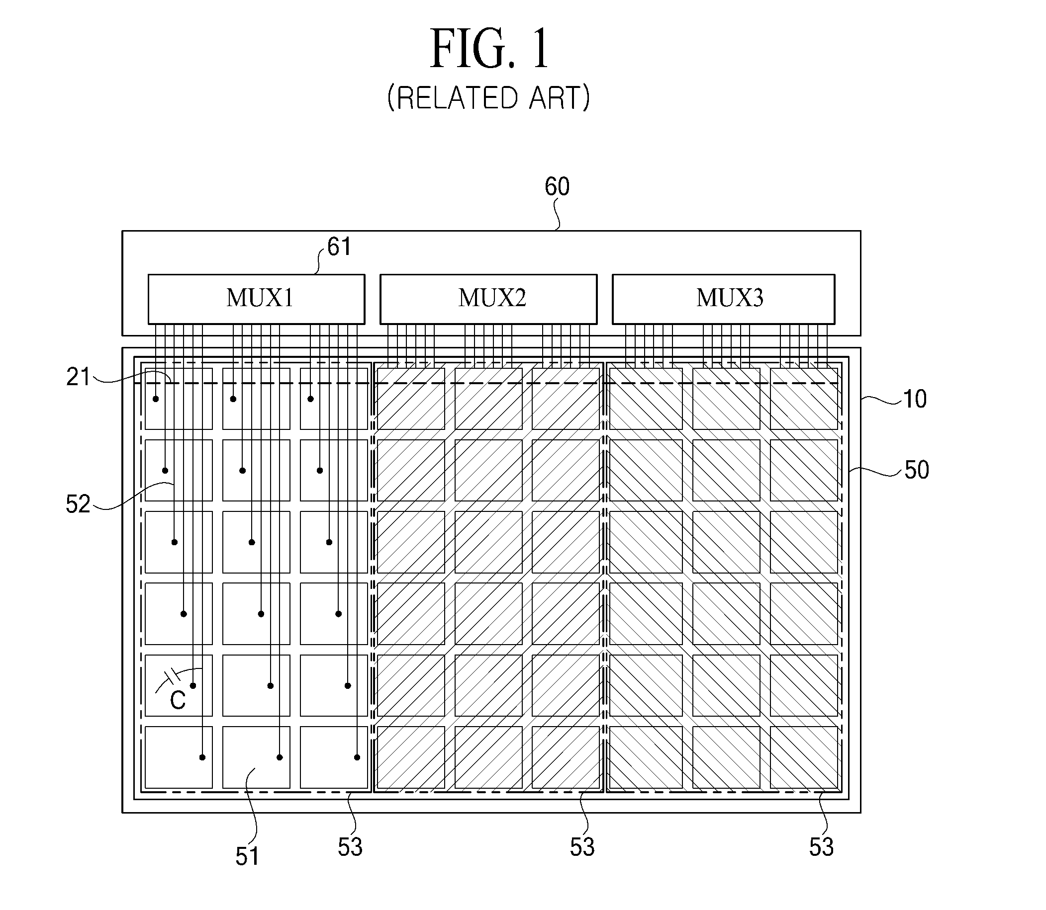
However, in the related art self-capacitance display device as illustrated in FIG. 1, when touch sensing is being performed with the touch groups 53 which are arranged along the data lines, a method of compensating for DTX becomes very complicated.
For this reason, a memory size associated with DTX compensation needs to be increased, and a complexity of calculation is also increased.
Consequently, there are many difficulties to eliminate the DTX and a large compensation error may occur.
For this reason, a large compensation error may occur.
Therefore, a parasitic capacitance C occurs between the touch lines 52 and the data lines, causing touch noise.
Moreover, when the self-capacitance type touch panel is implemented as an in-cell type, the magnitude of the DTX noise may be significantly increased.

Method used


Image

  • Display device and method of driving the same
  • Display device and method of driving the same
  • Display device and method of driving the same

Examples


Embodiment Construction

[0037]Reference will now be made in detail to the exemplary embodiments of the present invention, examples of which are illustrated in the accompanying drawings. Wherever possible, the same reference numbers will be used throughout the drawings to refer to the same or like parts.

[0038]Hereinafter, embodiments of the present invention will be described in detail with reference to the accompanying drawings. Hereinafter, for convenience of a description, an LCD device will be described as an example of the present invention, but the present invention is not limited thereto. That is, the present invention may be applied to various display devices.

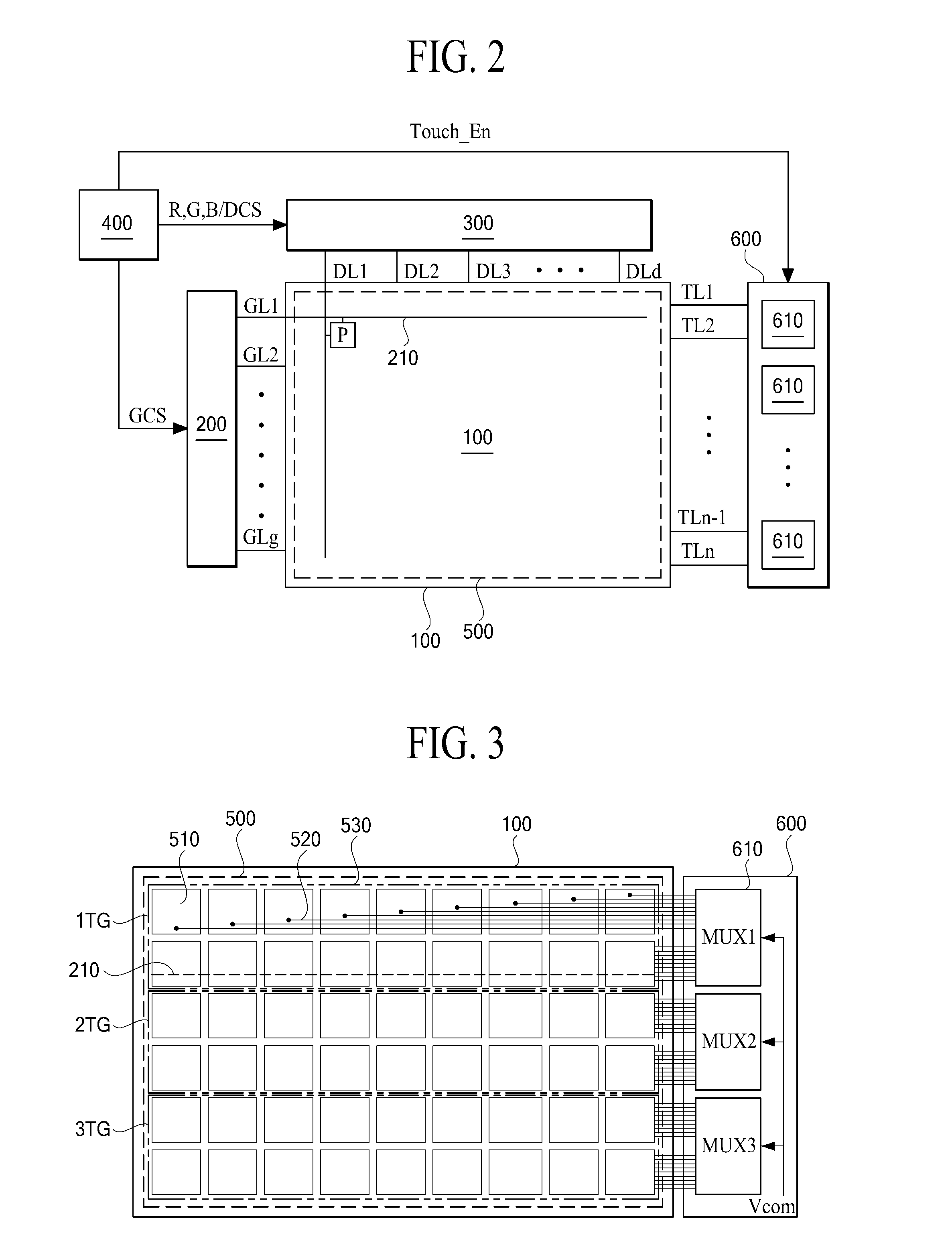
[0039]FIG. 2 is an exemplary diagram schematically illustrating a configuration of a display device according to an embodiment of the present invention. FIG. 3 is an exemplary diagram illustrating configurations of a panel and a touch sensing unit applied to a display device according to an embodiment of the present invention and illustrates a ...


PUM


Abstract

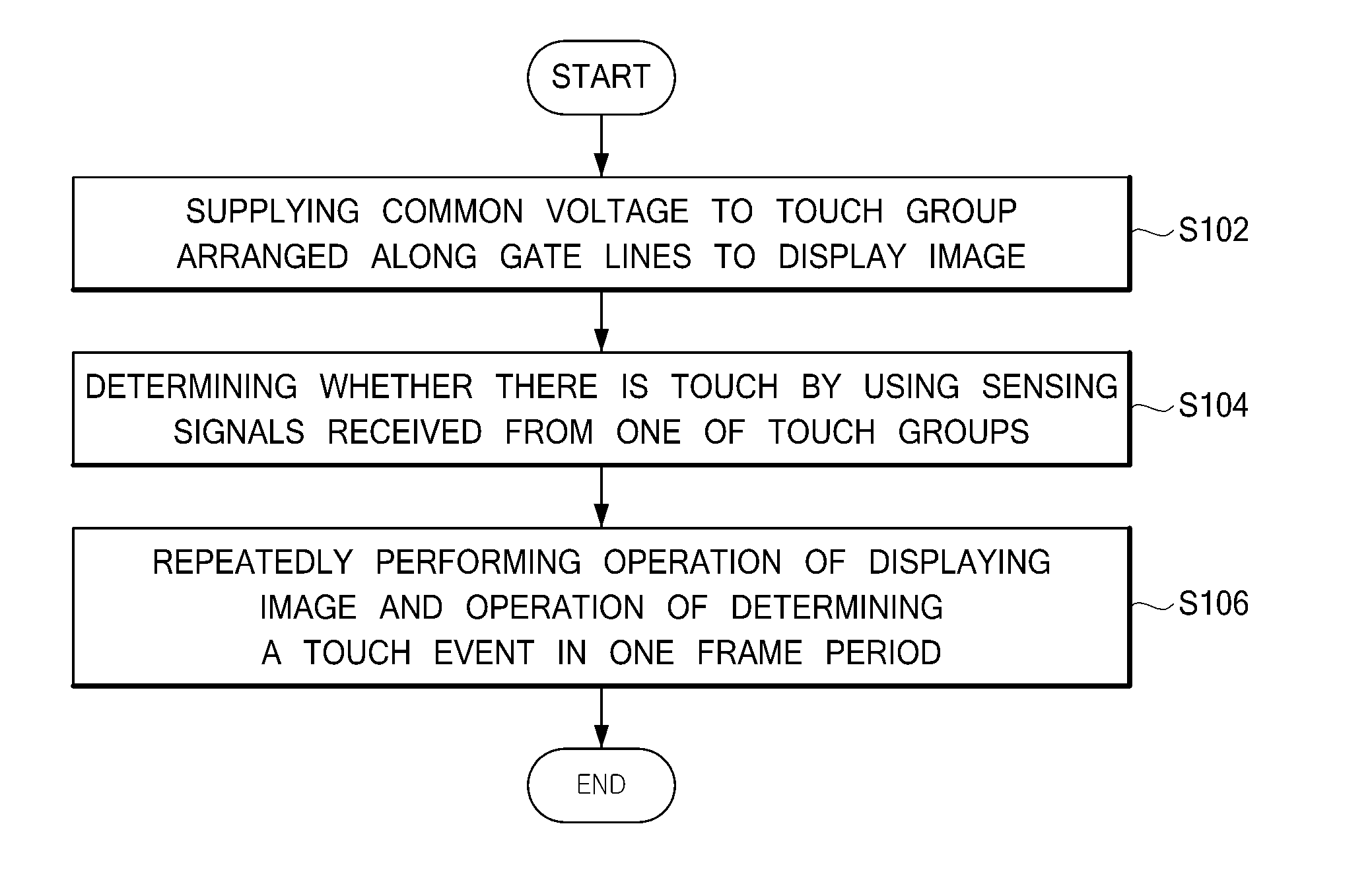
Discussed are a display device and a method of driving the same. The display device can include a panel where a plurality of touch groups including a plurality of self-capacitance electrodes are arranged along with a plurality of gate lines, a touch sensing unit configured to analyze a plurality of touch sensing signals sequentially received from the plurality of touch groups to determine a touch event on the panel, during a plurality of touch sensing periods included in one frame period, a data driver configured to respectively supply data voltages to a plurality of data lines which are provided in the panel in a direction perpendicular to the plurality of touch groups, a gate driver configured to sequentially supply a scan pulse to the plurality of gate lines, and a timing controller configured to supply image data to the data driver.

Description

CROSS-REFERENCE TO RELATED APPLICATIONS[0001]This application claims the priority benefit of the Korean Patent Application No. 10-2014-0050827 filed on Apr. 28, 2014, which is hereby incorporated by reference as if fully set forth herein.BACKGROUND[0002]1. Field of the Invention[0003]The present invention relates to a display device and a method of driving the same, and particularly, to a display device where a touch panel is integrated within a panel and a method of driving the same.[0004]2. Discussion of the Related Art[0005]Touch panels are coordinate input devices. Touch panels are attached to display devices such as liquid crystal display (LCD) devices, plasma display panels (PDPs), organic light emitting display device (OLED), and electrophoretic displays (EPDs). A touch panel enables a user to input information by directly touching the touch panel with a finger, a pen or the like while looking at the screen of the display device.[0006]A method of manufacturing an LCD device i...

Claims


Application Information

Patent Timeline
IPC IPC(8): G06F3/041G06F3/044
CPCG06F3/044G06F3/0418G06F3/0412G06F3/04166G06F3/04184G06F3/0443G06F3/0416G06F2203/04104
Inventor KIM, SUNG CHULKIM, HOON BAE
Owner LG DISPLAY CO LTD
Learn More