Load port unit and efem system

Inactive Publication Date: 2015-10-29
TDK CORPARATION
View PDF16 Cites 15 Cited by
  • Summary
  • Abstract
  • Description
  • Claims
  • Application Information

AI Technical Summary

Benefits of technology

[0007]The present invention has been made in view of the above-mentioned circumstances, and it is an object of the present invention to provide a load port unit as an interface that is reduced

Problems solved by technology

However, the pod is transported through an external space with less cleanliness and mounted on a load port unit, and hence it is a concern that dust or the like penetrates into the mini-environment or the oxygen concentration is increa

Method used


Image

  • Load port unit and efem system
  • Load port unit and efem system
  • Load port unit and efem system

Examples


Embodiment Construction

[0020]Preferred embodiments of the present invention will now be described in detail in accordance with the accompanying drawings.

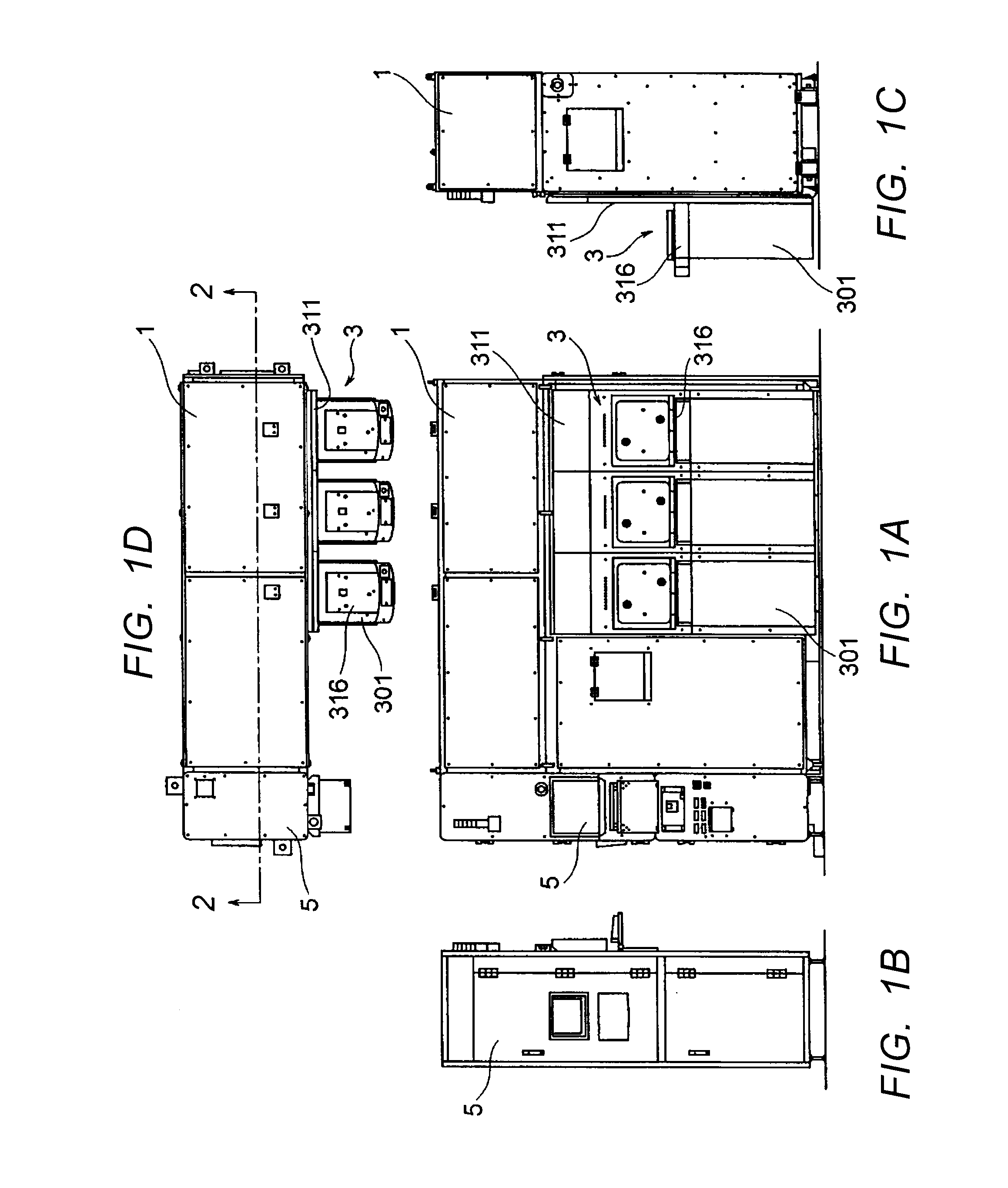
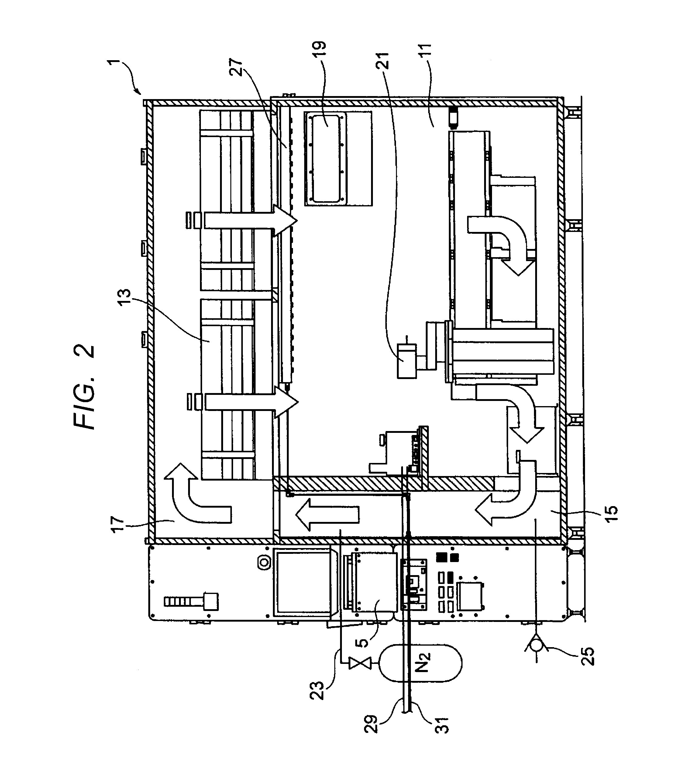
[0021]Exemplary embodiments of the present invention are described below with reference to the accompanying drawings. FIGS. 1A, 1B, 1C, and 1D are diagrams illustrating an exterior of an EFEM system 100 according to an embodiment of the present invention. FIG. 1A is a front view of the EFEM system, FIG. 1B is a side view of the EFEM system on the left side, FIG. 1C is a side view of the EFEM system on the right side, and FIG. 1D is a top view of the EFEM system. FIG. 2 is a schematic diagram illustrating an internal configuration of an EFEM unit on a cross section cut along the plane 2-2 of FIG. 1D.

[0022]The EFEM system 100 according to this embodiment includes, as main constituent elements, an EFEM unit 1, a load port unit 3, and a control unit 5. The control unit 5 controls an operation of each of drive elements and the like described later with respect...


PUM


Abstract

To suppress dust or the like from being drawn into a delivery zone when opening a lid of a pod in an EFEM system, a load port unit in the EFEM system includes a sealing member arranged on an external space side of a base, which defines a delivery zone and has an opening portion formed therein, and a sealing member arranged on the delivery zone side. A surface of a door that closes the opening portion on an external opening side protrudes toward the external space side with respect to an imaginary plane defined by a sealing region of the sealing member on the external opening side.

Description

BACKGROUND OF THE INVENTION[0001]1. Field of the Invention[0002]The present invention relates to a so-called equipment front end module (EFEM) system to be used in a semiconductor manufacturing process or the like when transporting a wafer held in a sealed transportation container referred to as a pod to a semiconductor processing apparatus or when transporting a wafer from the semiconductor processing apparatus to the pod, and further relates to a load port unit that actually performs opening and closing of a lid of the pod in the EFEM system.[0003]2. Description of the Related Art[0004]In recent years, in a semiconductor manufacturing process, there has generally been adopted a method of managing cleanliness throughout a process by maintaining a high cleanliness level in only three spaces including insides of various processing apparatus, a pod that contains a wafer and enables transportation of the wafer between the processing apparatus, and a mini-environment for performing deli...

Claims


Application Information

Patent Timeline
IPC IPC(8): H01L21/673H01L21/677
CPCH01L21/67742H01L21/67376H01L21/67017H01L21/67126H01L21/67772
Inventor MIYAJIMA, TOSHIHIKOIGARASHI, HIROSHI
Owner TDK CORPARATION
Why Eureka
Try Eureka