
Robotic Control System Using Virtual Reality Input

a robotic control system and input technology, applied in the field of robotic control, can solve the problems of poor adaptability of ai robotic control systems to uncertain, unfamiliar or changing environments, system limitation to the quality of input sources,

Active Publication Date: 2015-11-05
PARKER COLEMAN P
View PDF24 Cites 37 Cited by
  • Summary
  • Abstract
  • Description
  • Claims
  • Application Information

AI Technical Summary

Benefits of technology

This patent describes a system and method for autonomously performing tasks on real-world objects using a robotic system controlled by virtual reality technology. The system detects the presence of objects using sensors and captures data about them through a virtual world computer. The virtual world is then manipulated by a user through the user interface, and the resulting modifications are sent to the robotic system to execute the tasks autonomously. The system can identify specific objects of interest and use pre-defined rules to selectively execute tasks on them. The technical effects of this technology include improved efficiency and precision in performing tasks on real-world objects, as well as improved user experience and reliability through automation and virtual simulation.

Problems solved by technology

The system is limited to the quality of the input sources, the degree of pre-programmed responses and variation from the “example material” provided at programming time, and the actual material interacted with by the robot.
These AI robotic control systems tend to be poor at adapting to uncertain, unfamiliar or changing environments.
These control systems generally require prehandling of potential environmental inputs, and failure modes when an input is encountered that was not prepared for can range from ignoring that input to shutting down.
However, this approach still relies on a human operator to directly control the robot, e.g., in real time.

Method used


Image

  • Robotic Control System Using Virtual Reality Input
  • Robotic Control System Using Virtual Reality Input
  • Robotic Control System Using Virtual Reality Input

Examples


example

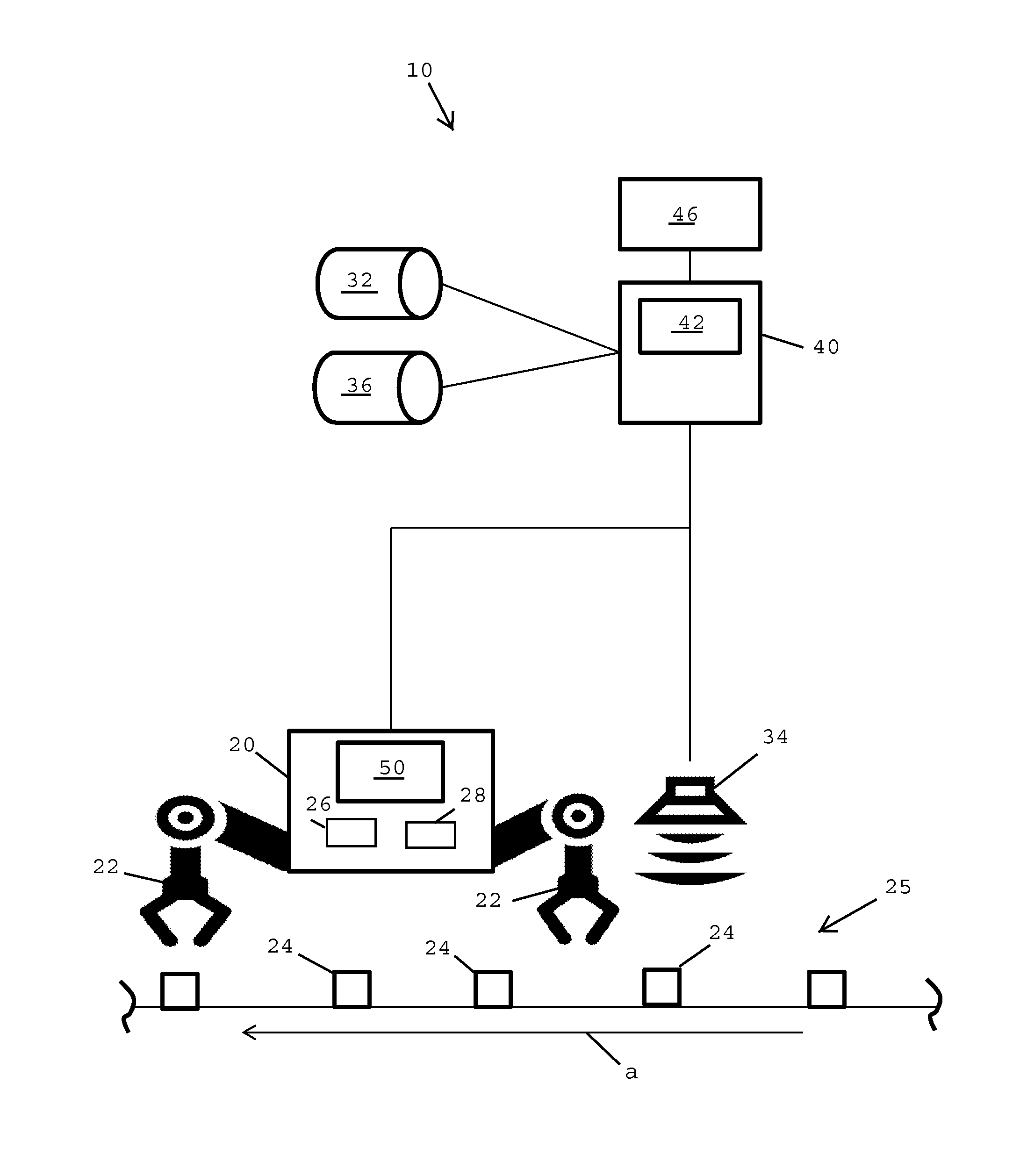
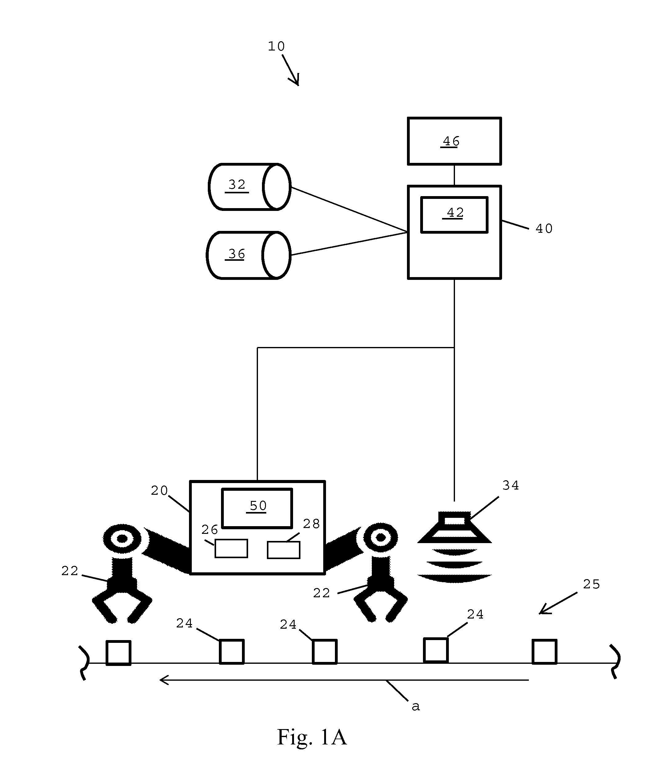
[0057]A prototype of system, substantially as shown and described with respect to FIGS. 1A-5, was built to find batteries and mercury containing Compact Fluorescent Lamp (CFL) light bulbs in a trash stream about to be burned. A USB video camera visual data source was used as sensor 34. A bright light was also used to provide higher contrast for the camera. The physical inputs 101 included a live video feed generated by the camera. A representative first set of rules 102 for the RWOs (CFLs) 24 were loaded onto data store 32, and included the size of the batteries and CFL bulbs, the best pickup location for a CFL, the best location to pick up a broken piece of glass, and the deposit location for each type of material picked up, in x,y coordinates. This set 102 also included data about the amount of broken CFL glass it was safe to leave, and the priority to use in removing batteries in the event more batteries were identified then could be removed, by ordering them from most to least h...


PUM


Abstract

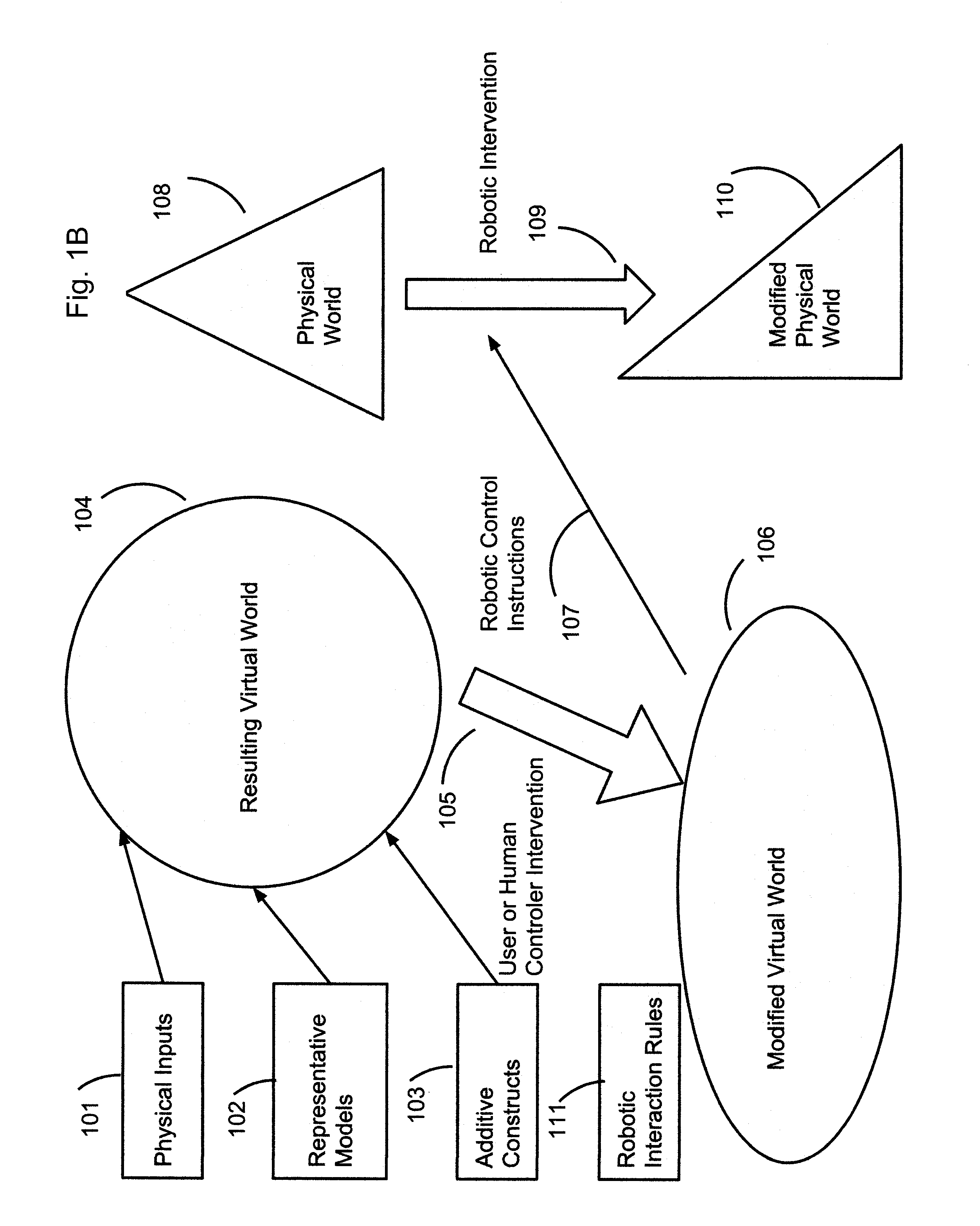
A robotic system and method performs tasks autonomously on real-world objects (RWOs) upon receipt of inputs from a virtual reality environment. A robotic actuator has tools to manipulate the RWOs, and a set of robot-specific instructions for actuating the tools. A first set of rules governs the RWOs, and sensors detect the presence of the RWOs. A virtual reality (VR) computer uses sensor data to generate a virtual world (VW) including virtual world objects (VWOs) representative of RWOs. A second set of rules governs the VWOs. A user manipulates the VWOs to generate a modified virtual world (MVW). A transformation engine captures differences between the VW and MVW, transforms the differences into inputs for the robotic actuator. An autonomous instruction engine receives the inputs to identify RWOs and combines the inputs with the first set of rules to generate combined instructions usable by the robotic actuator to manipulate RWOs autonomously.

Description

RELATED APPLICATION[0001]This application claims the benefit of U.S. Provisional Patent Application Ser. No. 61 / 986,282, entitled A System to Allow Manipulation in a Constructed Virtual / Game World to Result in Changes to the Physical World, filed on Apr. 30, 2014, the contents of which are incorporated herein by reference in their entirety for all purposes.BACKGROUND[0002]1. Technical Field[0003]This invention relates to robotic control, and more particularly to a system and method for permitting human manipulation of virtual objects in a randomly varying environment to generate inputs by which a robot interacts with corresponding real world objects autonomously.[0004]2. Background Information[0005]Throughout this application, various publications, patents and published patent applications are referred to by an identifying citation. The disclosures of the publications, patents and published patent applications referenced in this application are hereby incorporated by reference into ...

Claims


Application Information

Patent Timeline
Patent Type & Authority Applications(United States)
IPC IPC(8): B25J9/16B25J13/08
CPCB25J9/1612B25J9/163G05B2219/40053G05B2219/39543B25J13/08B25J9/1689G05B2219/40131
Inventor PARKER, COLEMAN P.
Owner PARKER COLEMAN P
Learn More