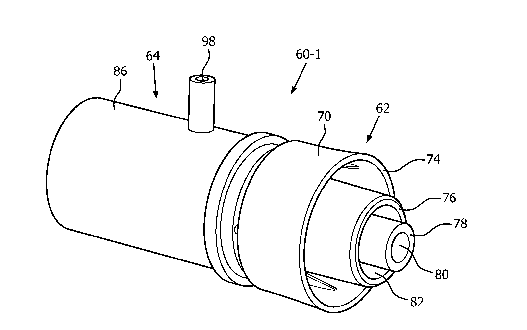
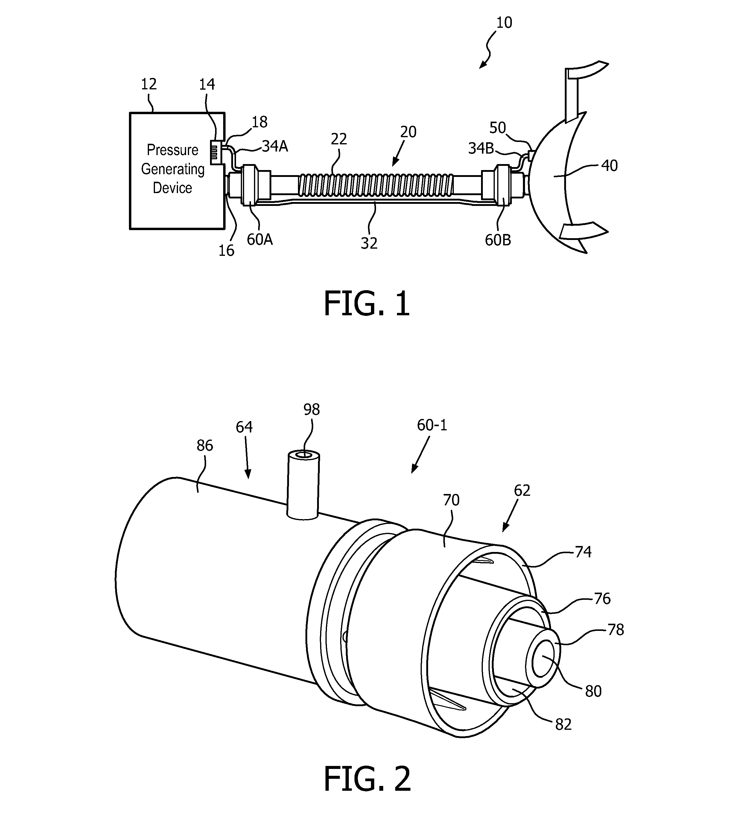
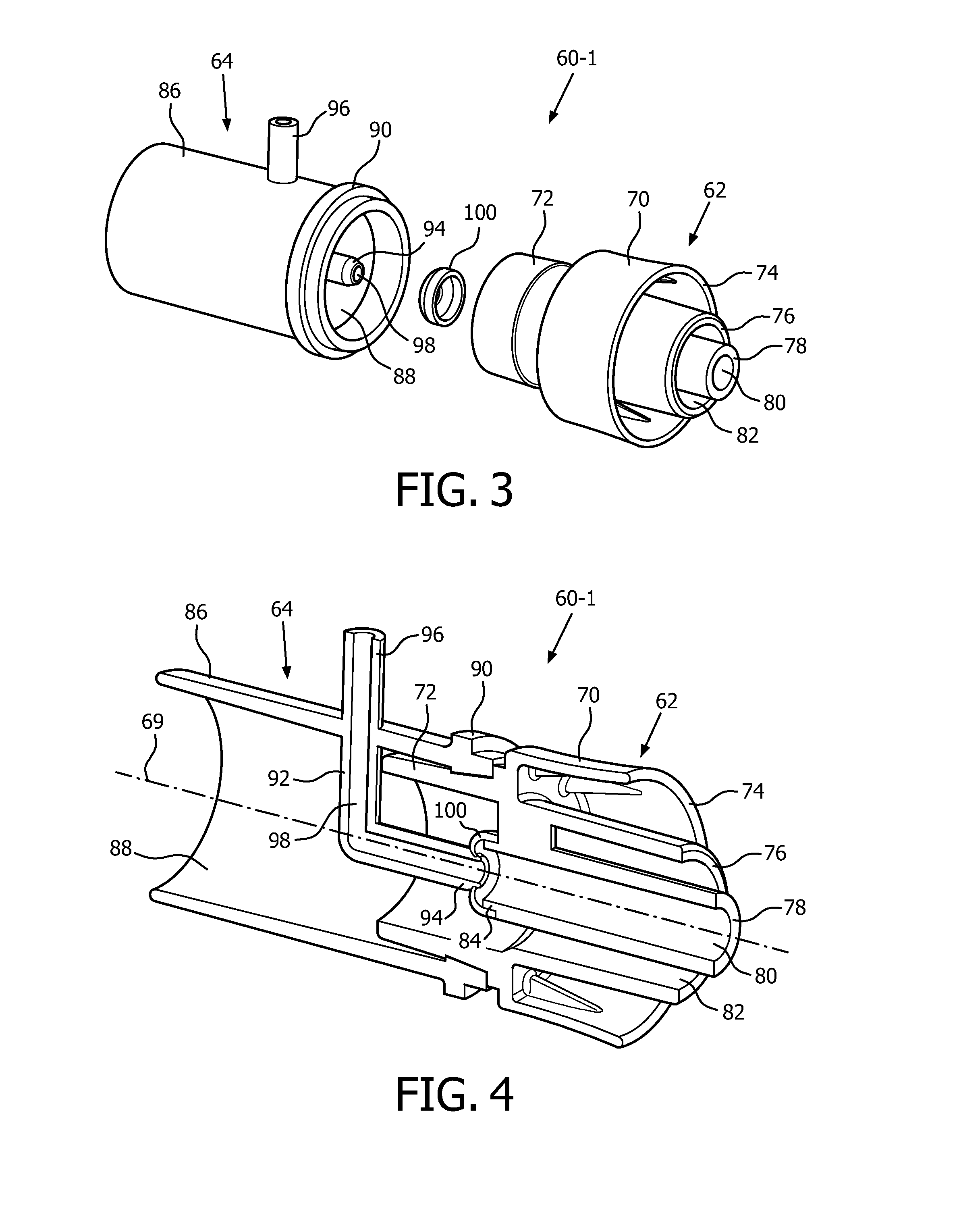
Rotary fluid coupler

a fluid coupler and rotary technology, applied in the direction of respirator, other medical devices, life-saving devices, etc., can solve the problem of limiting the ability of the delivery conduit to rota

Inactive Publication Date: 2015-11-12
KONINKLJIJKE PHILIPS NV
View PDF15 Cites 61 Cited by
  • Summary
  • Abstract
  • Description
  • Claims
  • Application Information

AI Technical Summary

Benefits of technology

[0009]These and other objects, features, and characteristics of the present invention, as well as the methods of operation and functions of the related elements of structure and the combination of parts and economies of manufacture, will become more apparent upon consideration of the following description and the appended claims with reference to the accompanying drawings, all of which form a part of this specification, wherein like reference numerals designate corresponding parts in the various figures. It is to be expressly understood, however, that the drawings are for the purpose of illustration and description only and are not intended as a definition of the limits of the invention.

Problems solved by technology

However, a traditional delivery conduit (e.g., a traditional hose) connected to a traditional rotary coupler or swivel port can experience undesirable tangling / twisting due to the pressure tube, which often limits the ability of the delivery conduit to rotate.

Method used


Image

  • Rotary fluid coupler
  • Rotary fluid coupler
  • Rotary fluid coupler

Examples


Embodiment Construction

[0023]As used herein, the singular form of “a,”“an,” and “the” include plural references unless the context clearly dictates otherwise. As used herein, the statement that two or more parts or components are “coupled” shall mean that the parts are joined or operate together either directly or indirectly, i.e., through one or more intermediate parts or components, so long as a link occurs. As used herein, “directly coupled” means that two elements are directly in contact with each other. As used herein, “fixedly coupled” or “fixed” means that two components are coupled so as to move as one while maintaining a constant orientation relative to each other.

[0024]As used herein, the word “unitary” means a component is created as a single piece or unit. That is, a component that includes pieces that are created separately and then coupled together as a unit is not a “unitary” component or body. As employed herein, the statement that two or more parts or components “engage” one another shall...


PUM


Abstract

A system for delivering a flow of breathing gas to a patient that includes a main delivery conduit coupled to a gas source, and a rotary coupling device coupled to the main delivery conduit and having a first member and a second member, the first member defining a first channel and a second channel through the first member, the second member defining a third channel and a fourth channel through the second member. The first channel is in communication with the third channel to define a main channel having a main path, and the second channel is in communication with the fourth channel to define a secondary channel separate from the main channel and having a secondary path. The first member and the second member are structured to freely ro tate relative to one another in a manner that separately maintains the main path and the secondary path.

Description

BACKGROUND OF THE INVENTION[0001]1. Field of the Invention[0002]The present invention pertains to fluid coupling devices, and, in particular, to a rotary fluid coupling device that has multiple, separate channels and that allows for portions of the coupling device to rotate relative to one another while maintaining the integrity of the separate channels. Such a rotary fluid coupling device would, for example, be useful in a medical application, such as a pressure support system for treating sleep apnea, wherein breathing gas would delivered to the patient through one channel of the coupling device and the other channel or channels would be used for another purpose, such as pressure monitoring or the delivery of supplemental oxygen to the patient.[0003]2. Description of the Related Art[0004]There are numerous situations where it is necessary or desirable to deliver a flow of breathing gas non-invasively to the airway of a patient, i.e., without intubating the patient or surgically in...

Claims


Application Information

Patent Timeline
Patent Type & Authority Applications(United States)
IPC IPC(8): A61M16/08A61M16/00
CPCA61M16/0816A61M16/0003A61M2205/3331A61M16/0057A61M2016/0027A61M16/0875A61M16/14A61M39/10A61M39/105A61M39/1055A61M2039/082A61M2202/0208A61M2206/18A61M16/0486A61M16/0638A61M16/085A61M16/0858
Inventor BAFILE, ANTHONY JONSHELLY, BENJAMIN IRWIN
Owner KONINKLJIJKE PHILIPS NV
Why Eureka
Try Eureka