Vehicle drive device

a technology of vehicle drive and axial dimension, which is applied in the direction of electric devices, fluid gearings, gearings, etc., can solve the problems of reducing the capability and efficiency of fluid coupling [the torque converter b>1/b>], and it is difficult to reduce the radial dimension of the drive device. , the effect of reducing the length

Inactive Publication Date: 2013-08-01
AISIN AW CO LTD +1
View PDF5 Cites 33 Cited by
  • Summary
  • Abstract
  • Description
  • Claims
  • Application Information

AI Technical Summary

Benefits of technology

[0028]According to this configuration, the inner periphery-side fixing portion of the disk-like member is fixed to the joint member by using the rivet that extends through the inner periphery-side fixing portion in the direction parallel to the axis direction. Rivets typically can reduce the length in the axial dir...

Problems solved by technology

This increases the radial dimension around the coupling-side joint portion, thereby making it difficult to reduce the radial dimension of the drive device.
Accordingly, if vehicles do not have enough mount spac...

Method used


Image

  • Vehicle drive device
  • Vehicle drive device
  • Vehicle drive device

Examples


Embodiment Construction

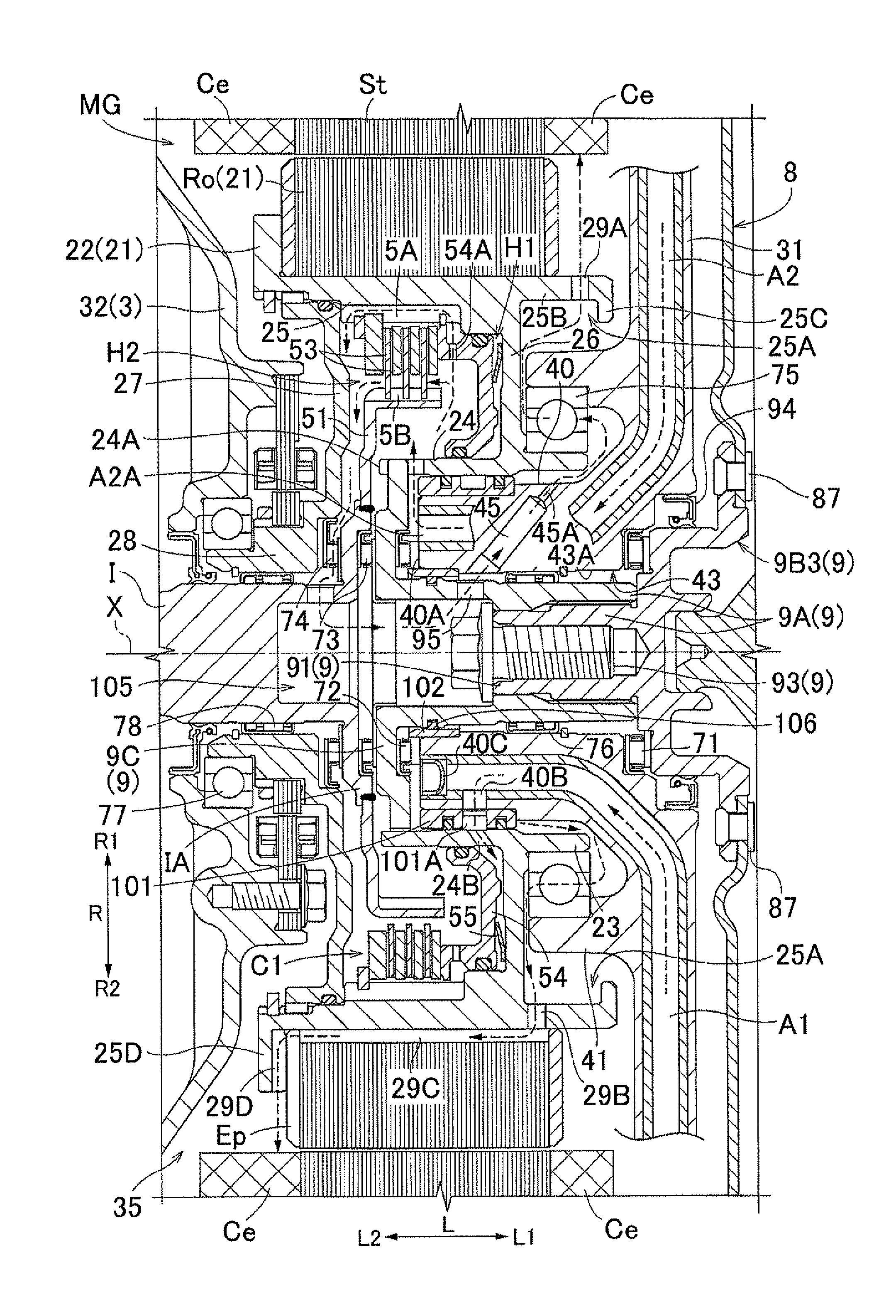
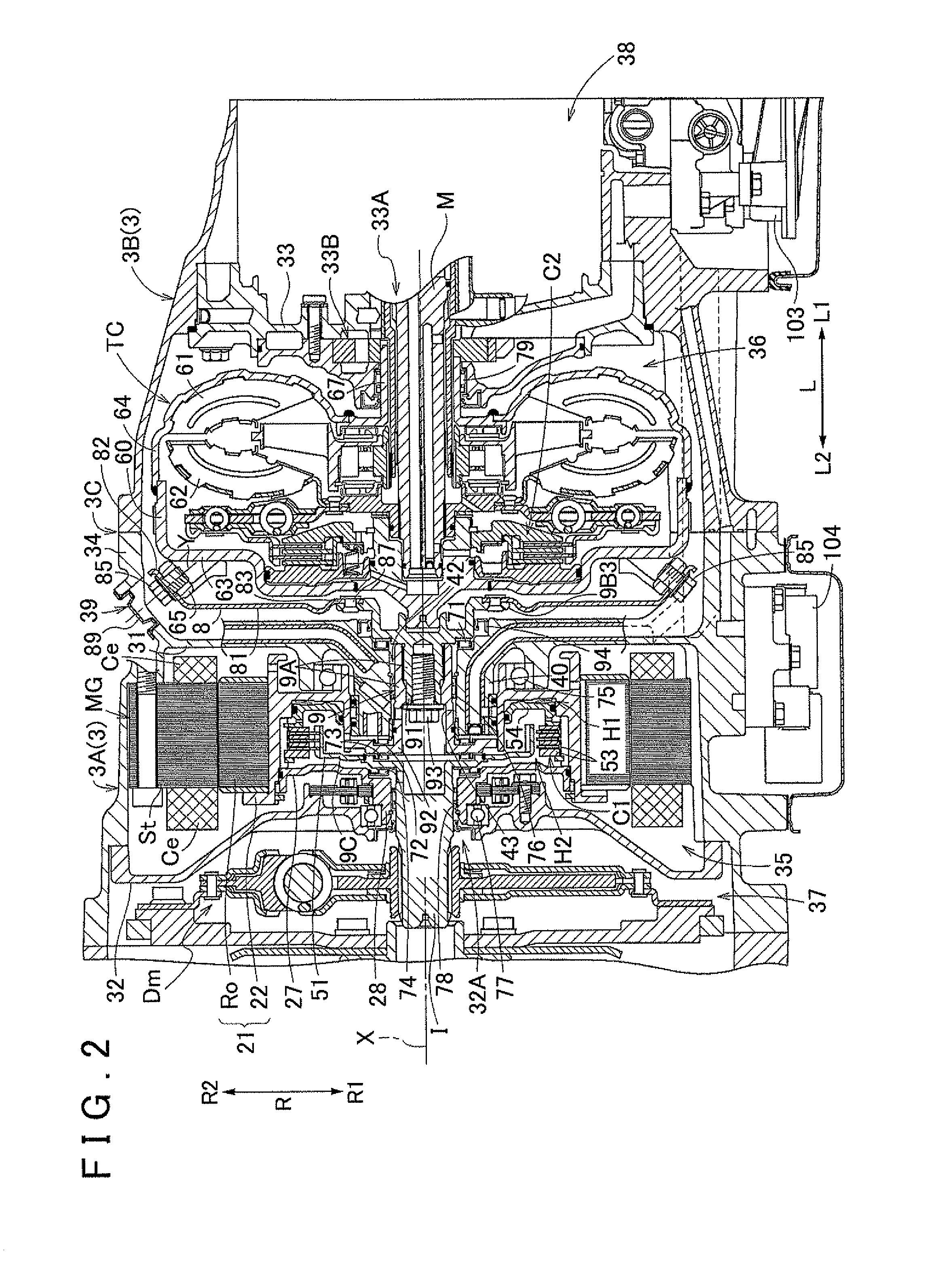
[0033]An embodiment of a vehicle drive device according to the present invention will be described with reference to the accompanying drawings. In the following description, the “axial direction L,” the “radial direction R,” and the “circumferential direction” are defined based on the central axis of rotation (the central axis X shown in FIG. 2) of a rotating electrical machine MG unless otherwise specified. The “axial first direction L1” represents the direction from the rotating electrical machine MG toward a torque converter TC along the axial direction L (the right direction in FIG. 2), and the “axial second direction L2” represents the direction opposite to the axial first direction L1 (the left direction in FIG. 2). The “radially inward direction R1” represents the direction that is inward in the radial direction R, and the “radially outward direction R2” represents the direction that is outward in the radial direction R. The direction of each member represents the direction o...


PUM


Abstract

A vehicle drive device includes a rotating electrical machine; and a fluid coupling on one side and coaxial with the electrical machine. A rotor is coupled to a housing of the fluid coupling via a disk-like member. The disk-like member is coaxial with the electrical machine, and includes a main body, and an outer fixing portion. The main body is disk-shaped and between the electrical machine and the fluid coupling. The fluid coupling includes joint fixed to the outer fixing portion. The outer fixing portion has a truncated conical surface, a diameter of which increases from the electrical machine to the fluid coupling. The joint is fixed to the rotary housing where it overlaps the rotary housing viewed in an axial direction, and includes a contact surface contacted by the outer fixing portion. The contact surface does not overlap the electrical machine as viewed perpendicular to the contact surface.

Description

INCORPORATION BY REFERENCE[0001]The disclosure of Japanese Patent Application No. 2012-017310 filed on Jan. 30, 2012 and U.S. Provisional Application No. 61 / 592,226 filed on Jan. 30, 2012 including the specification, drawings and abstract is incorporated herein by reference in its entirety.BACKGROUND OF THE INVENTION[0002]The present invention relates to vehicle drive devices that include a rotating electrical machine, and a fluid coupling placed on one side in the axial direction of the rotating electrical machine with respect to the rotating electrical machine and coaxially with the rotating electrical machine.DESCRIPTION OF THE RELATED ART[0003]Regarding such vehicle drive devices, there is a technique described in, e.g., Japanese Patent Application Publication No. 2006-137406 (JP 2006-137406 A) (FIGS. 1 to 3). In the description of the section “Description of the Related Art,” the names of the members in Patent Document 1 are shown in parenthesis (“[ ]”). As shown in FIG. 1 of t...

Claims


Application Information

Patent Timeline
IPC IPC(8): H02K7/00B60L50/16
CPCH02K7/003B60K6/387F16H41/24H02K7/006Y02T10/6221B60K6/48F16H2057/02034F16H57/025B60K6/405B60L3/0061B60L15/2054B60L2220/50B60L2240/36B60L2240/486B60L2240/507B60L50/16Y02T10/62Y02T10/64Y02T10/7072Y02T10/72Y02T10/70
Inventor IWASE, MIKIOSUYAMA, DAIKIJINNAI, NAOYAOKISHIMA, TATSUYAINOUE, YUJIIDESHIO, YUKIHIKO
Owner AISIN AW CO LTD
Why Eureka
Try Eureka