Fluid Coupling Assembly with Integral Retention Mechanism

a technology of integral retention mechanism and coupling assembly, which is applied in the direction of pipe joints, pipe elements, engine seals, etc., can solve the problems of adding additional problems, and achieve the effect of reducing the possibility of foreign object debris and damage, and facilitating the mating of teeth

Active Publication Date: 2007-11-22
SPS TECH LLC
View PDF5 Cites 33 Cited by
  • Summary
  • Abstract
  • Description
  • Claims
  • Application Information

AI Technical Summary

Benefits of technology

[0012] The present invention is directed to an improved fluid coupling assembly for retaining a sealed joint by fastening two components together. One of the components includes a serrated annular surface. The other component has an axially aligned flexible projection to contact the serrated annular surface to enable a relatively low force rotation during a sealing engagement of a first sealing surface on the first component and a second sealing surface on the second component. A relatively higher force resistance is provided between the serrated annular surface and the axial flexible projection during a disengagement rotation to thereby ensure the security of the predetermined seating torque between the pair of components.
[0018] The first component member can have an approximately cylindrical configuration with a central cylindrical axial bore extending through a male projection having external helical threads for rotation within a hollow opening of the second component member that has interior complimentary helical threads for providing a fastening between the two component parts. Adjacent to the annular serrations on the first component member can be a multi-flat facet surface forming in essence a nut configuration to assist in rotating the first component so that a first sealing surface on the male projection can engage a second sealing surface provided, for example, on a ferrule-tube fitting that can be welded to a fluid conduit.
[0023] In an alternative embodiment, a subjective balance force can be achieved in both coupling and de-coupling modes of operation. The teeth on the cantilevered beams and the annular serrated teeth can be uniformly rounded. By removing any bias structure or configurations on the contact surface of the annular serrations, the manufacturing cost can be lessened and foreign object debris and damage can be reduced. Also by rounding the contact surface on the annular serrations, less wear and tear is experienced on both component members.
[0026] An increase of the number of teeth on each axially projecting member can further help distribute the pressure during contact and further reduce the possibility of foreign object debris and damage.
[0027] Finally, an axial chamfer of a gentle and smooth configuration can further facilitate a mating of the teeth and annular serrations during coupling.

Problems solved by technology

These factors can cause both a loosening and releasing of a desired seal ceding torque between a pair of interfacing components.
In the aircraft field wherein the fluid coupling assembly is utilized in pneumatic and hydraulic connectors, there is not only temperature, external vibrations and stress problems, but also pressure stresses from the fluid that is being conducted through the sealed joint which can add additional problems.

Method used


Image

  • Fluid Coupling Assembly with Integral Retention Mechanism
  • Fluid Coupling Assembly with Integral Retention Mechanism
  • Fluid Coupling Assembly with Integral Retention Mechanism

Examples


first embodiment

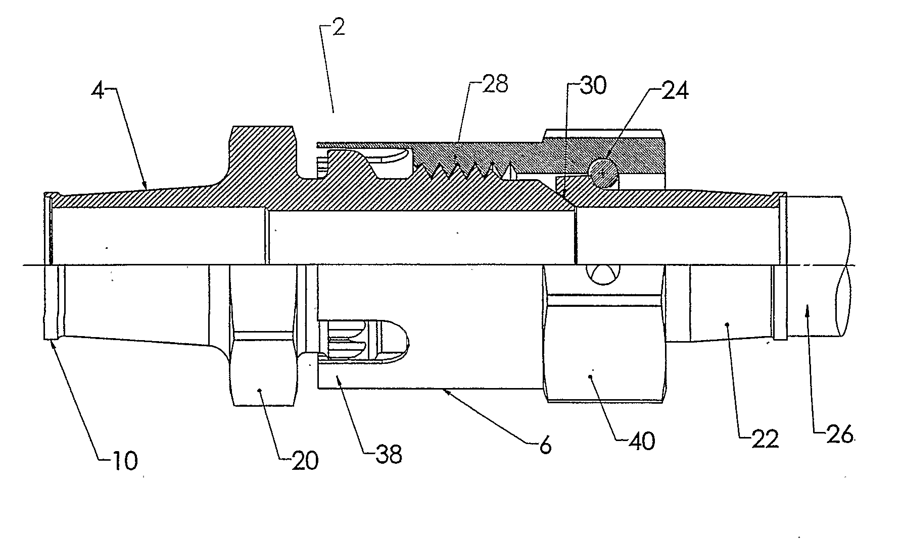
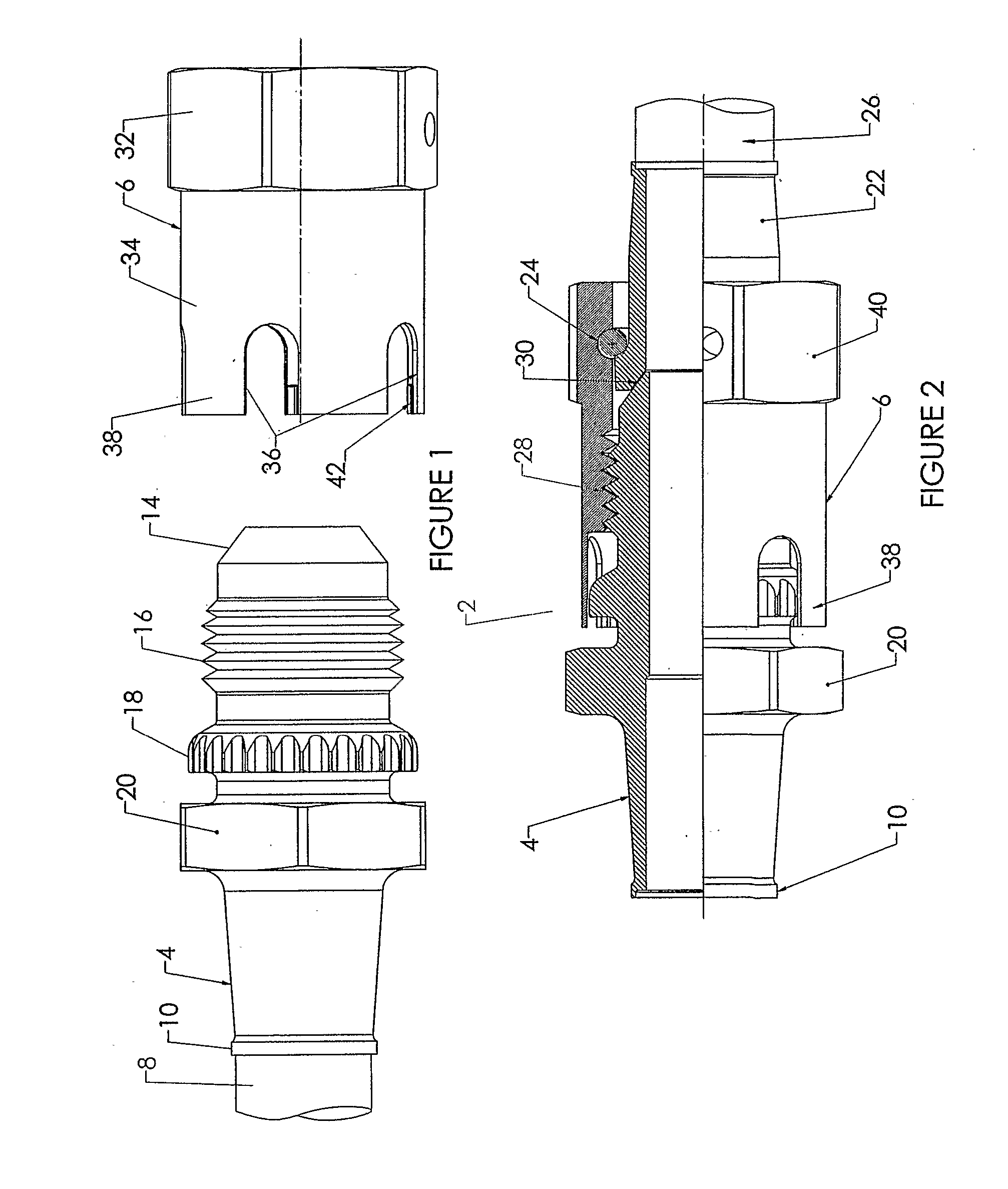
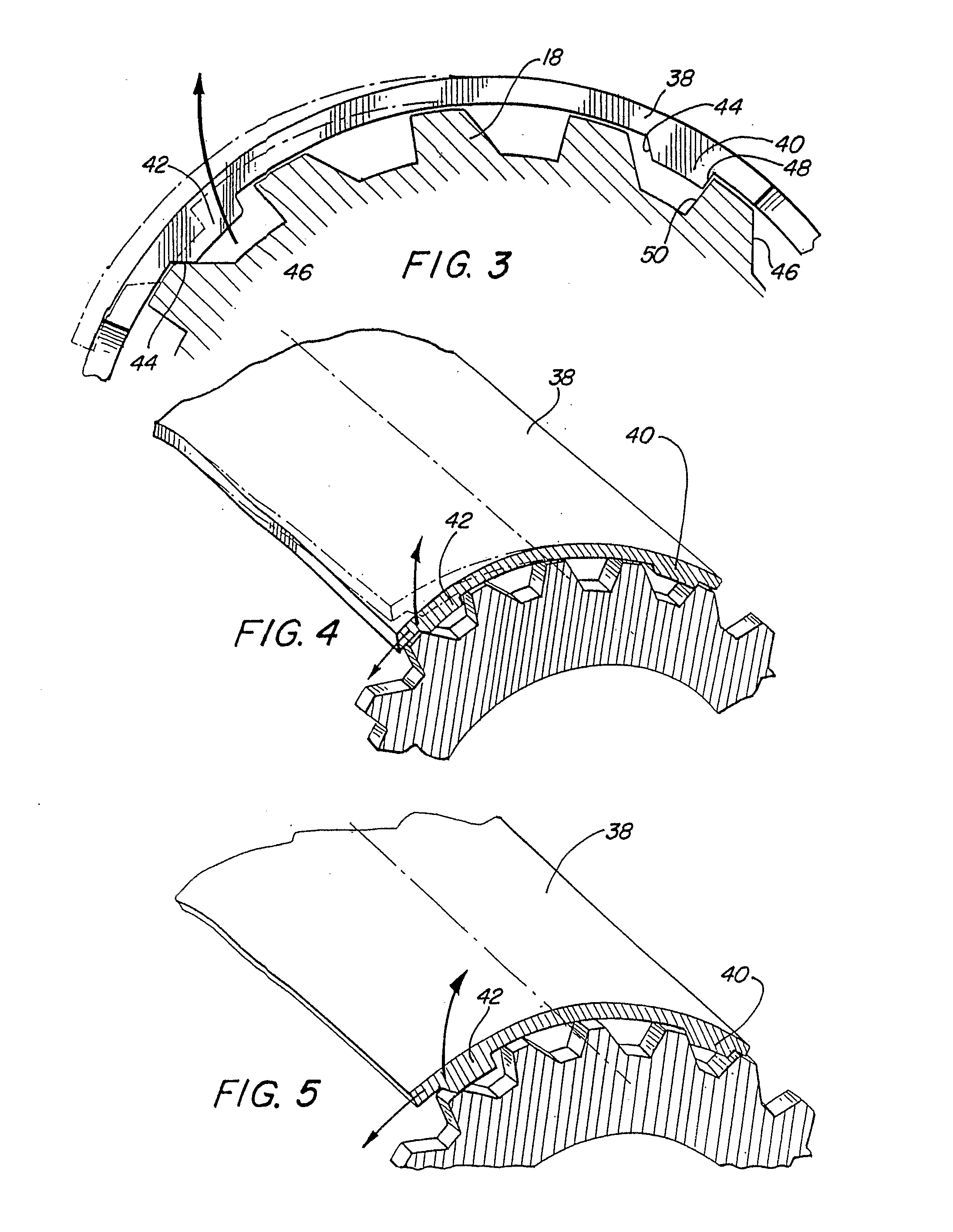
[0043] Referring to FIG. 3, a schematic cross-sectional view is disclosed of the present invention, wherein the serrations or detents 18 are shown relative to a pair of spaced teeth 40 and 42 extending radially inward for engagement with the serrations 18. The serrations 18 are annularly arranged in a circular pattern about the exterior of the first coupling member 4, and the axial cantilevered beams 38 have inner and outer diameters that subscribe concentric circles with the respective teeth members 40 and 42 projecting radially inward from the distal ends of the cantilevered beam inner diameter to engage the circular serrations 18 in a ratchening manner as the respective teeth undulate over the circular serrations 18 during sealing engagement and disengagement modes of operation.

[0044]FIG. 4 is another perspective view disclosing the relative flex of a cantilevered beam 38 as a sloping camming surface 44 on tooth 42 engages the corresponding sloping surface 46 of the serrations. A...

second embodiment

[0046]FIG. 8 discloses a schematic cross-sectional view of the axially cantilevered beam 38, serrations 58 and plurality of teeth 60. In the second embodiment any differential force can be achieved in both coupling and de-coupling modes of operation by the slope of the teeth 18 forming the annular serration.

[0047] By manufacturing the cantilevered teeth on the second coupling member 56, so that the teeth are of a rounded or a sinusoidal configuration, the manufacturing costs are significantly lessened and foreign object debris and damage can be reduced. Thus, less wear and tear is experienced. Since the leading surface and the trailing surface of the teeth have the same slope any difference in the forces exerted during coupling and the forces exerted during de-coupling of the second embodiment will depend upon the first coupling member and the degree of slope on the initial camming face of each serration tooth and the degree of slope on the locking face on the other side of the teet...


PUM


Abstract

The fluid coupling assembly for retaining a sealed joint includes the first member adapted to be connected to a first fluid conduit with a per sealing surface and a series of axially aligned serrations along with helical threads. A second member of a complementary configuration is adapted to be connected to a second fluid conduit with complementary threads and an axially extending cylindrical collar with spaced axial notches forming cantilevered beams. Each of the cantilevered beams can have teeth capable of engaging a series of serrations to provide an appropriate resistant force for both sealing engagement and disengagement. The teeth and serrations can remain in contact to provide a visual determination of a pretorqued force between the first member and the second member.

Description

BACKGROUND OF THE INVENTION [0001] 1. Field of the Invention [0002] The present invention is directed to a coupling joint assembly for retaining a sealed joint by fastening two components together and more particularly to an improved fluid coupling assembly that can be scaled to maintain its pre-lube characteristics for different size fluid paths. [0003] 2. Description of Related Art [0004] The necessity to couple and uncouple fluid lines or conduits, for example, associated with aircraft engines has been recognized in the prior art. Such coupling assemblies require a high degree of reliability to maintain a mechanical coupling of two component parts during use while subject to a substantial application of temperature ranges, stress vibration and movement. These factors can cause both a loosening and releasing of a desired seal ceding torque between a pair of interfacing components. In general, coupling two component parts together has frequently utilized the respective threads in a...

Claims


Application Information

Patent Timeline
Patent Type & Authority Applications(United States)
IPC IPC(8): F16L25/00
CPCF16L19/005F16L19/025F16L19/0225
Inventor PATEL, NILESH C.
Owner SPS TECH LLC
Why Eureka
Try Eureka