
Control apparatus for dynamic power transmission apparatus

a control apparatus and power transmission technology, applied in the direction of battery/fuel cell control arrangement, electric devices, gearing, etc., can solve the problems of excessive power consumption, insufficient driving torque for vehicle running, and increase the temperature of the clutch, so as to suppress an excessive power consumption, increase the speed of the electric motor, and dynamic

Active Publication Date: 2017-01-12
TOYOTA JIDOSHA KK
View PDF2 Cites 34 Cited by
  • Summary
  • Abstract
  • Description
  • Claims
  • Application Information

AI Technical Summary

Benefits of technology

The patent is about a control system for a vehicle that can manage the output of power without causing damage to the vehicle's mechanical parts. When the vehicle is running and the engine is generating power, the control system increases the speed of the electric motor to consume the excess power and ensure that the engine produces enough torque. This relieves the restriction of power generation and ensures that the vehicle has sufficient torque to run. The control system also ensures that the electric motor consumes the same amount of power as the engine, reducing power consumption. Overall, the control system optimizes power output and ensures that the vehicle runs safely and efficiently.

Problems solved by technology

Further, the apparatus described in JP 2014-113895 slips a clutch provided on the output side of the electric motor, and thereby, consumes the excess energy.
However, as described in JP 2014-113895, when the energy is consumed by the friction of the clutch, the energy is changed to heat, and therefore, there is a possibility that the temperature of the clutch increases and the durability decreases.
Further, if the electricity generation quantity in the electric generator is restricted for the maintenance of the durability of the clutch, the torque by the electric generator is restricted in addition to the restriction of the output of the engine, and therefore, there is a possibility that the driving torque for vehicle running is insufficient.
The electronic controller is configured to control the fluid coupling to differentially rotate and to drive the electric motor by the electric power such that a dynamic power loss is generated in the fluid coupling, when restricting the charge of the electric storage apparatus.
In that case, the torque of the electric motor is controlled such that the excess power with which the electric storage apparatus cannot be charged is equal to the power loss.

Method used


Image

  • Control apparatus for dynamic power transmission apparatus
  • Control apparatus for dynamic power transmission apparatus
  • Control apparatus for dynamic power transmission apparatus

Examples


Embodiment Construction

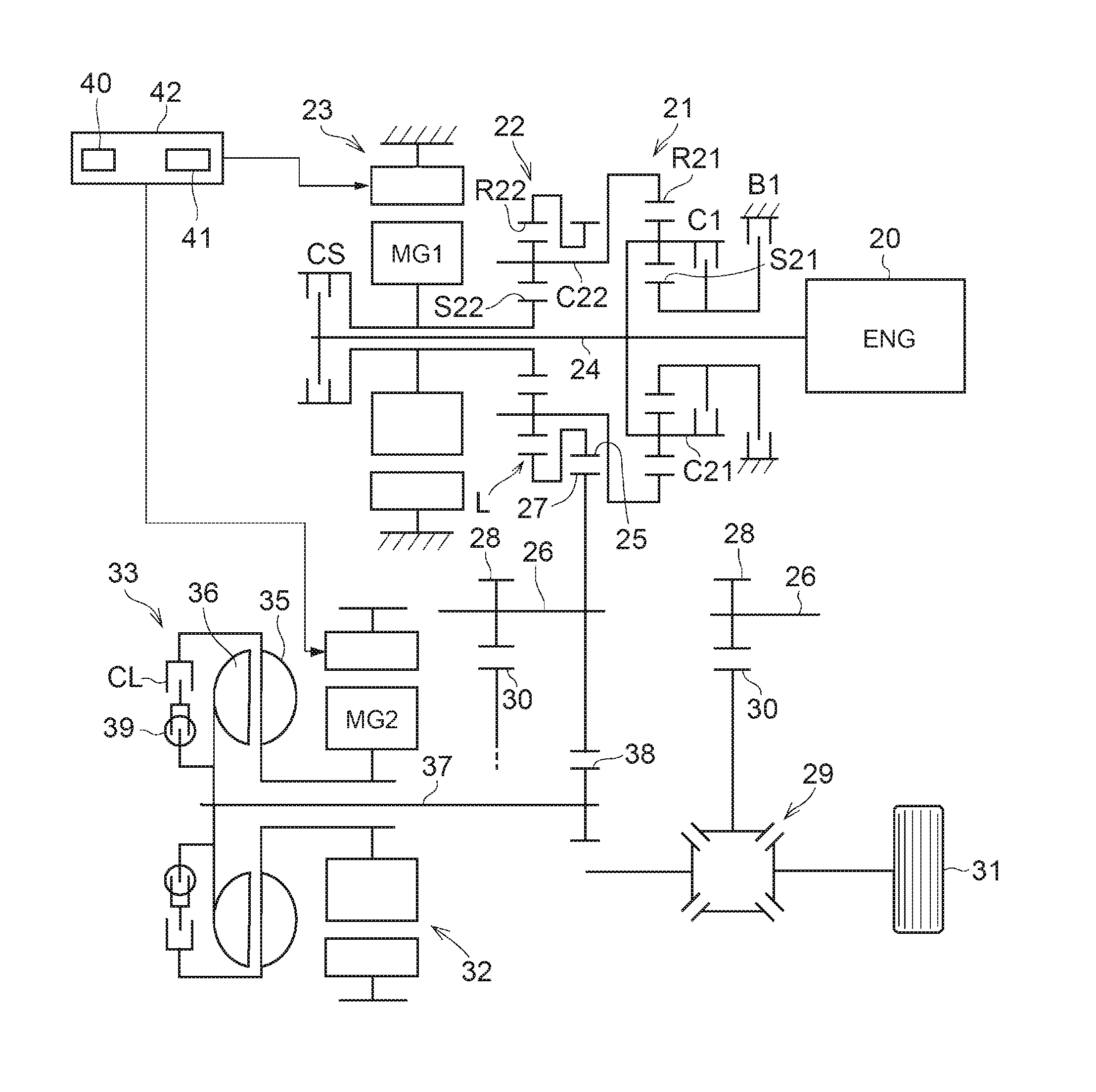
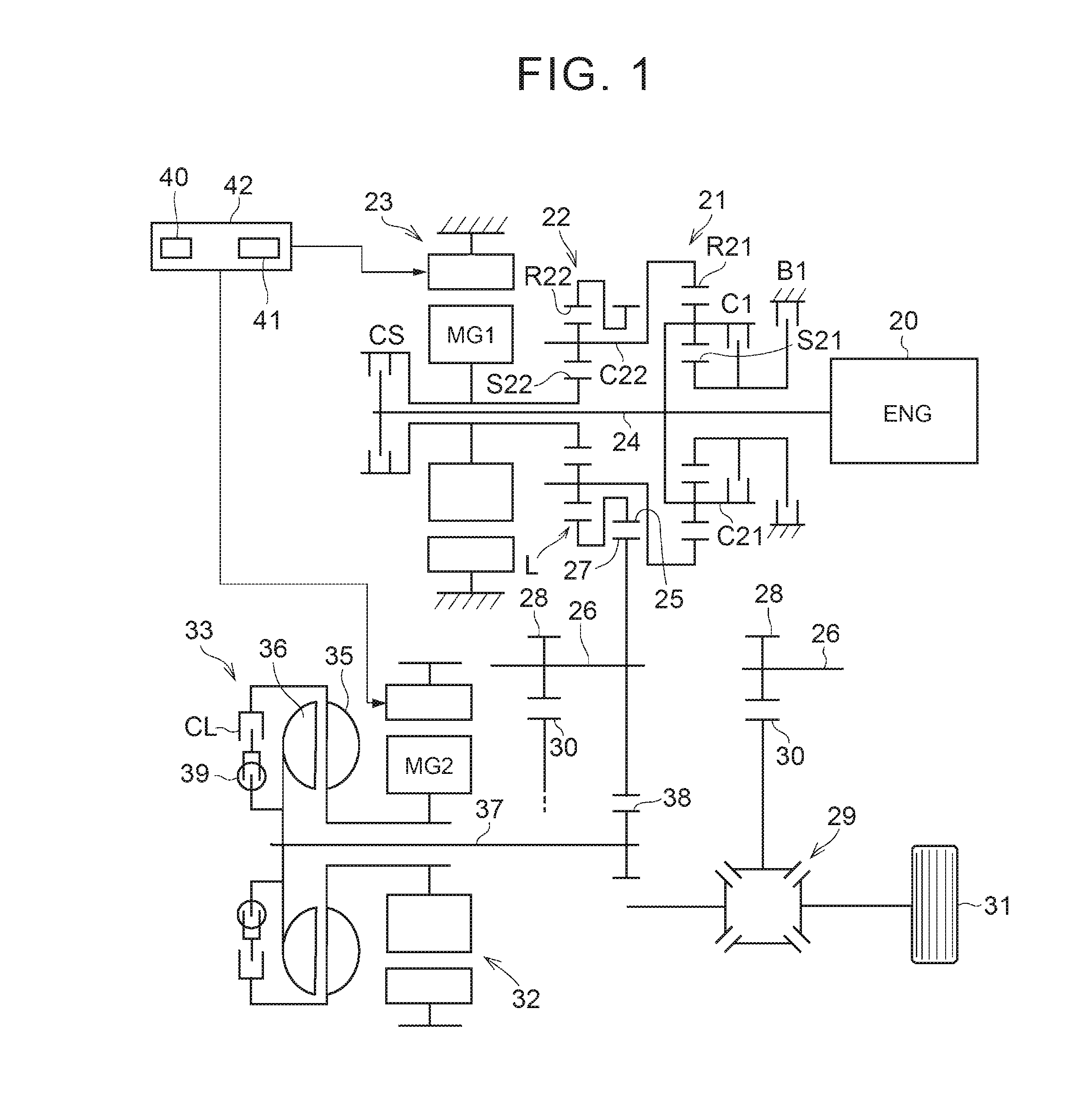
[0027]FIG. 1 shows an exemplary gear train of a dynamic power transmission apparatus of a hybrid vehicle that is controlled by a control apparatus in the disclosure. On an identical axis line to an engine (ENG) 20, an overdrive mechanism 21, a dynamic power division mechanism 22, and a first motor generator (MG1) 23 are disposed in order from the engine 20 side. The engine 20 is an internal combustion engine such as a gasoline engine or a diesel engine. The overdrive mechanism 21 is a mechanism for increasing the output speed such that the output speed is higher than the engine speed, and in the example shown in FIG. 1, is configured by a single pinion type planetary gear mechanism. Therefore, the overdrive mechanism 21 includes a sun gear S21, a ring gear R21 disposed on a circle concentric with the sun gear S21, and a carrier C21 holding, in a rotatable and revolvable manner, a pinion gear engaged with the sun gear S21 and the ring gear R21. The carrier C21 is linked with an input...


PUM


Abstract

A control apparatus for a dynamic power transmission apparatus is provided. The dynamic power transmission apparatus includes a differential mechanism, an electric generator, an electric motor, and a fluid coupling. The electric motor is disposed at a position apart from a transmission path along which a dynamic power of an engine is transmitted to a driving wheel. The fluid coupling is disposed between the electric motor and the transmission path. The control apparatus includes an electronic controller configured to restrict a charge of an electric storage apparatus with an electric power generated by the electric generator, depending on a state of the electric storage apparatus, and control the fluid coupling to differentially rotate and to drive the electric motor by the electric power such that a dynamic power loss is generated in the fluid coupling, when restricting the charge of the electric storage apparatus.

Description

CROSS-REFERENCE TO RELATED APPLICATIONS[0001]This application is based upon and claims the benefit of priority from Japanese Patent Application No. 2015-138618, filed on Jul. 10, 2015, the entire contents of which are incorporated herein by reference in entirety.BACKGROUND OF THE DISCLOSURE[0002]1. Field of the Disclosure[0003]The present application relates to a control apparatus for a dynamic power transmission apparatus including an engine, an electric generator, and an electric motor.[0004]2. Description of Related Art[0005]Japanese Patent Application Publication No. 2014-113895 describes a hybrid-vehicle power train including a hybrid driving apparatus and a 4-speed automatic transmission. The hybrid driving apparatus is configured to link an engine and an electric generator with a differential mechanism, to control engine speed by an electric motor, to amplify engine torque, to output the engine torque from the differential mechanism, to drive the electric motor by the electri...

Claims


Application Information

Patent Timeline
Patent Type & Authority Applications(United States)
IPC IPC(8): B60W20/13B60K6/54F16H3/72F16H37/08B60W10/26B60W10/08B60L50/15B60L50/16
CPCB60W20/13B60W10/26B60W10/08F16H3/728F16H37/0833B60K6/54B60Y2300/82B60W2710/083B60W2510/0666B60W2710/244F16H61/48F16H2200/2007F16H2200/2038B60W2510/244B60K6/442B60W10/02B60W10/06B60W20/20B60W2520/10B60W2540/10B60W2510/081B60W2710/0616B60W2710/0666B60W2710/025B60W2540/215B60K17/02B60K28/165B60L15/10B60L15/2054B60L2260/14B60K6/445B60Y2200/92Y02T10/72B60L58/12B60L58/25Y02T10/62Y02T10/64Y02T10/70B60W10/026B60W10/023B60W10/12B60W20/00B60K6/38B60K6/26B60K6/34B60K6/543B60L3/0046B60W20/10
Inventor IMAMURA, TATSUYATABATA, ATSUSHIOKUDA, KOICHIMATSUBARA, TOORUHIASA, YASUHIROIMAI, KEITAKITAHATA, TAKESHI
Owner TOYOTA JIDOSHA KK
Learn More