Braking system for a railway car

a technology for railway cars and brakes, applied in the direction of rail brake actuation, rail braking systems, brake arrangement with braking members, etc., can solve the problems of difficulty and complications during installation, single lever design offers little adjustability, and certain brake pads may wear more quickly

Active Publication Date: 2015-11-12
AMSTED RAIL CO INC
View PDF23 Cites 18 Cited by
  • Summary
  • Abstract
  • Description
  • Claims
  • Application Information

AI Technical Summary

Problems solved by technology

However, the single lever design offers little adjustability in the amount of divergent braking force generated.
When larger brake cylinders a

Method used


Image

  • Braking system for a railway car
  • Braking system for a railway car
  • Braking system for a railway car

Examples


Embodiment Construction

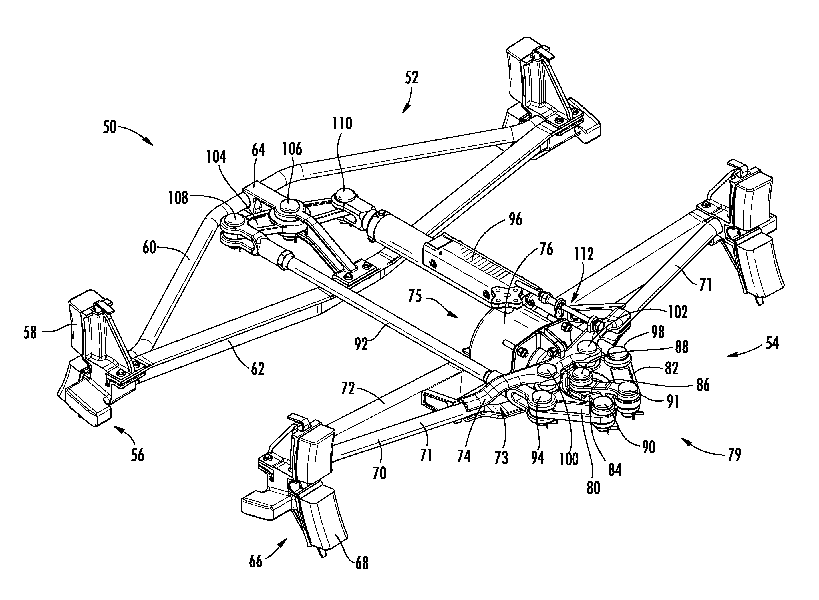
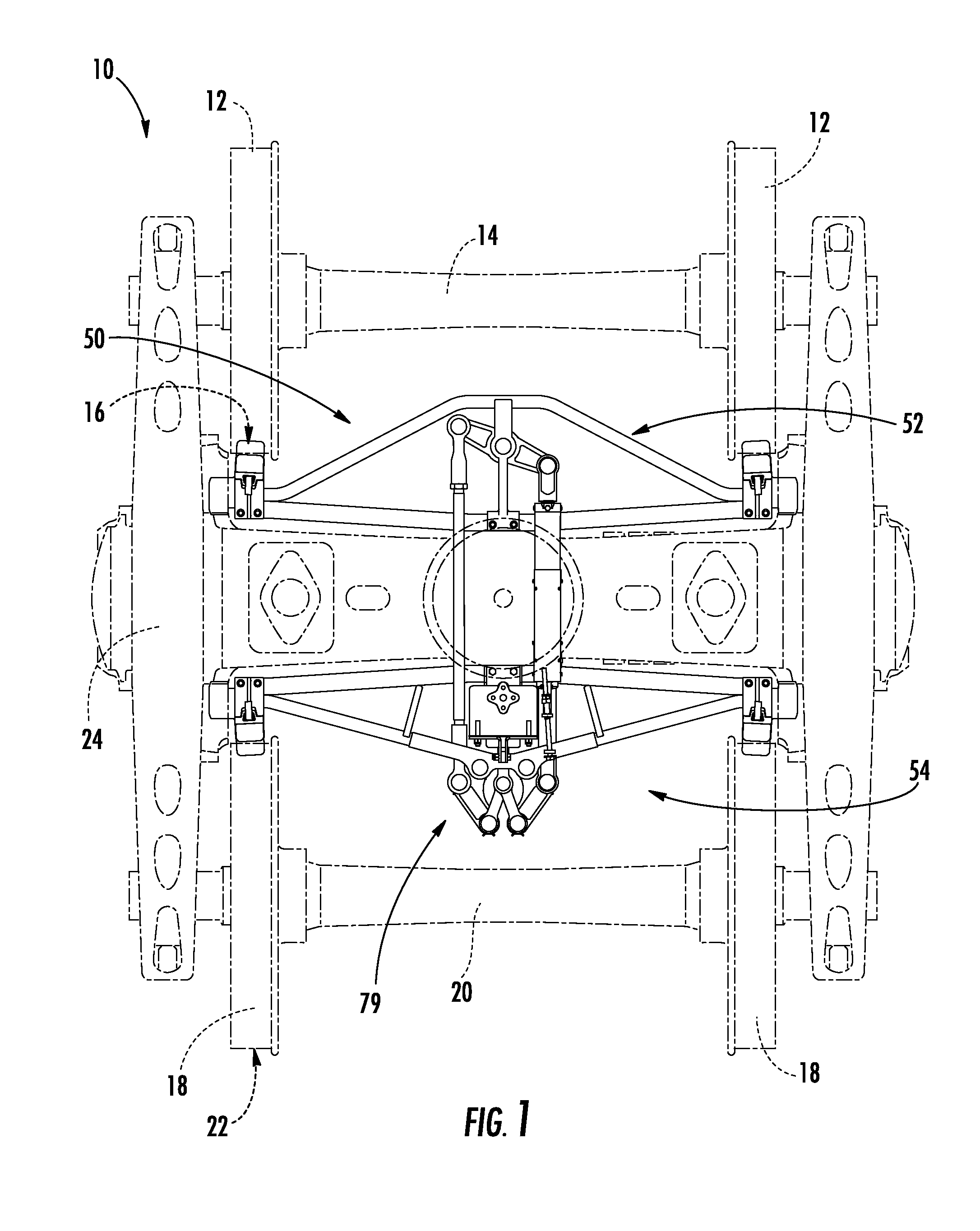
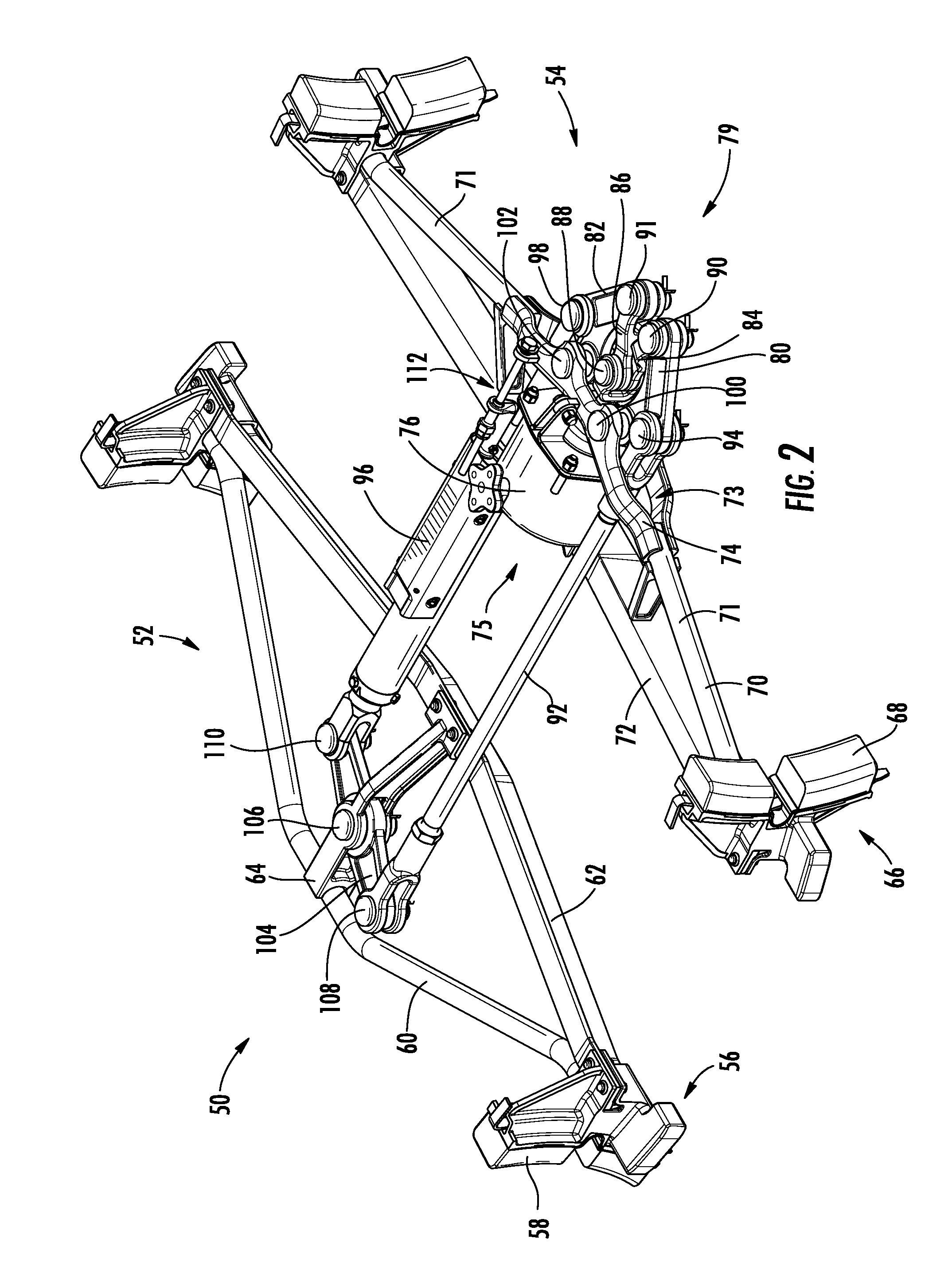
[0020]Reference will now be made in detail to present embodiments of the invention, one or more examples of which are illustrated in the accompanying drawings. The detailed description uses numerical and letter designations to refer to features in the drawings. Like or similar designations in the drawings and description have been used to refer to like or similar parts of the invention. As used herein, the terms “first”, “second”, and “third” may be used interchangeably to distinguish one component from another and are not intended to signify location or importance of the individual components. Similarly, the terms “front” and “rear” may be used to describe certain components relative to one another, it being understood that the orientation of the components may be reversed depending on a traveling direction of the railway car. Moreover, the term “longitudinally” refers to the relative direction substantially parallel to the traveling direction of a railway car, and “radially” refer...


PUM


Abstract

The present invention includes a braking system for a railway car generally including a brake cylinder having a cylinder rod. The cylinder rod is in mechanical communication with a lever transfer assembly and is configured to articulate said lever transfer assembly. The lever transfer assembly may be rotatably connected to a first brake assembly and connected to a rear brake assembly through respective connection rods. Actuating the lever transfer assembly with the cylinder rod generates a divergent braking force between the first and second brake assemblies for slowing and/or stopping the railway car.

Description

FIELD OF THE INVENTION[0001]The present invention generally relates to a braking system for a railway car, or more particularly to a braking system for a railway car including a lever transfer system.BACKGROUND OF THE INVENTION[0002]Railway cars are widely used for transportation of goods and passengers throughout the United States and abroad. Railway cars generally include one or more truck assemblies including a plurality of specially designed wheels for traveling along a vast infrastructure of railway tracks. Braking systems are generally disposed between adjacent pairs of wheels for facilitating the stopping or slowing down of the railway car.[0003]The braking systems generally include front and rear brake assemblies, each including a pair of brake heads with brake pads for contact with an outer periphery of the wheels when the front and rear brake assemblies are moved away from one another. Commonly, an air cylinder including a cylinder rod is provided in the braking system for...

Claims


Application Information

Patent Timeline
IPC IPC(8): B61H13/32B61H15/00B61H1/00
CPCB61H13/32B61H15/0007B61H1/00B61H13/36
Inventor SUNDE, JONATHAN
Owner AMSTED RAIL CO INC
Why Eureka
Try Eureka