Vacuum powered resin loading system without central control

Inactive Publication Date: 2015-11-12
MAGUIRE STEPHEN B
View PDF14 Cites 17 Cited by
  • Summary
  • Abstract
  • Description
  • Claims
  • Application Information

AI Technical Summary

Benefits of technology

[0067]This use of multiple flow limiters to allow different line sizes in the same resin conveying system is an important aspect of this invention. Such use of multiple fl

Problems solved by technology

Many large central systems often have too much capacity

Method used


Image

  • Vacuum powered resin loading system without central control
  • Vacuum powered resin loading system without central control
  • Vacuum powered resin loading system without central control

Examples


Embodiment Construction

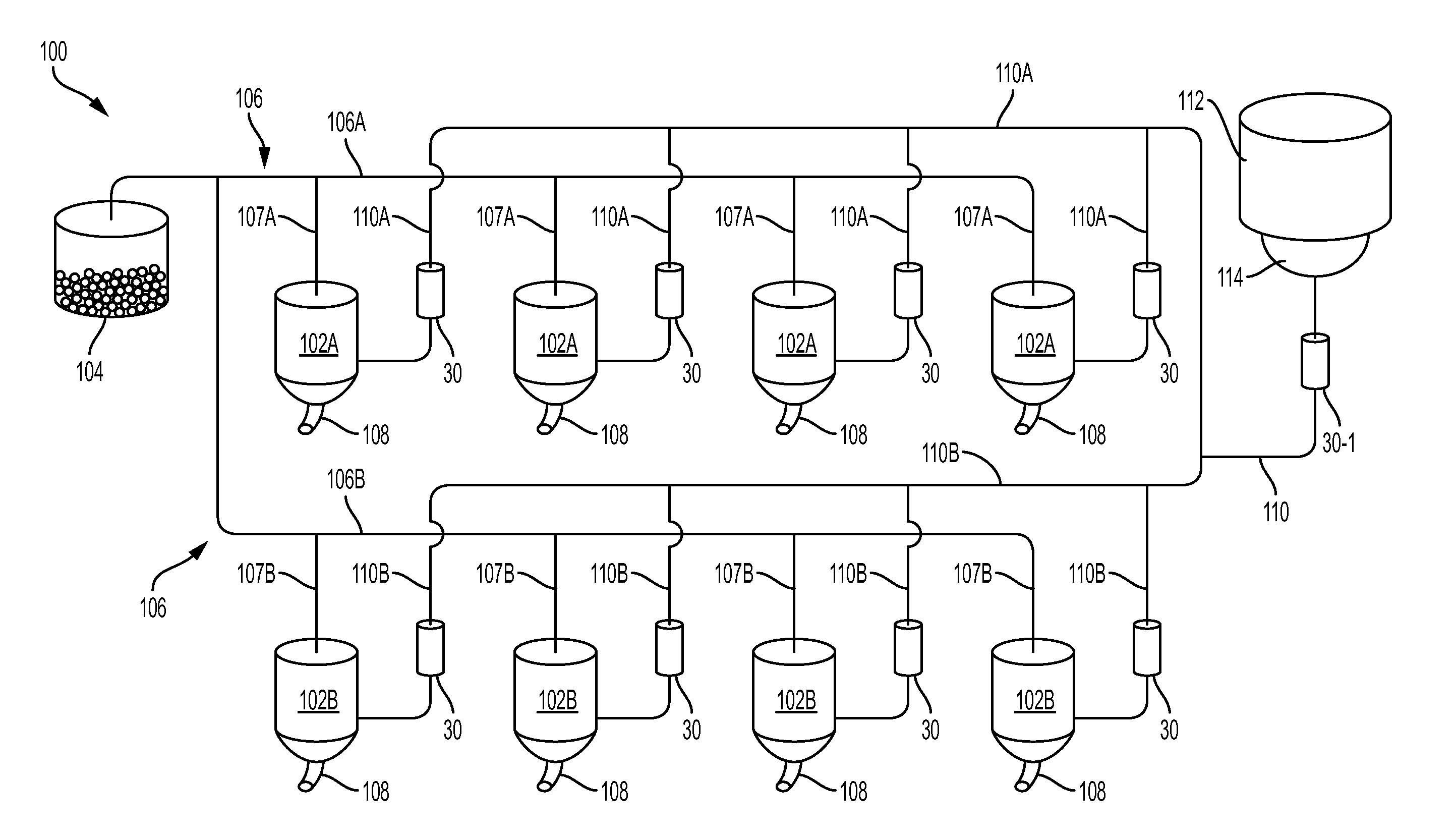
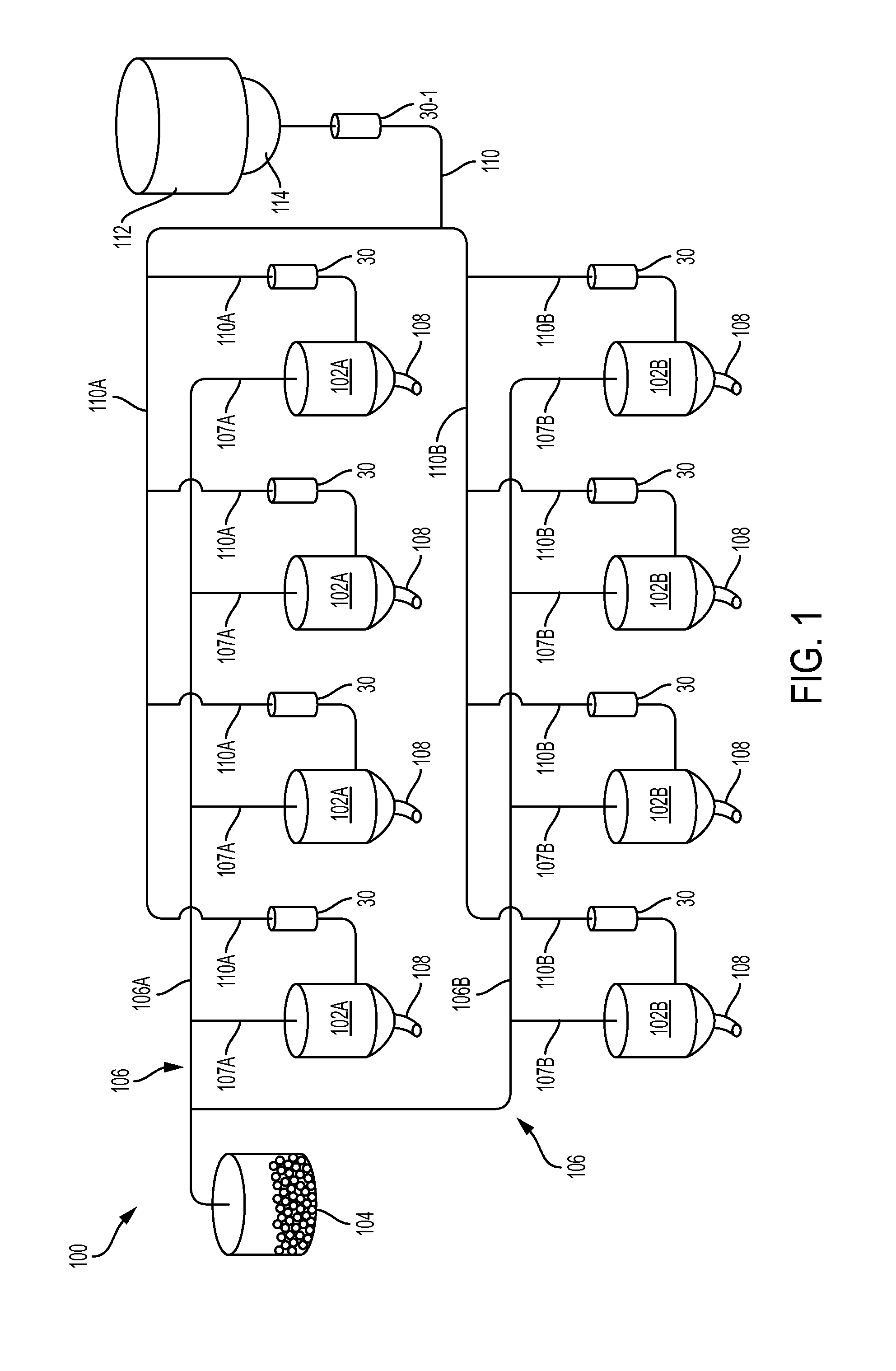
[0087]Referring to the drawings in general and to FIG. 1 in particular, apparatus for delivery of granular plastic resin material in accordance with the invention is designated generally 100. Apparatus 100 conveys granular plastic resin material from a resin material supply 104 to a plurality of receivers, each of which is designated either 102A or 102B in FIG. 1. The resin is conveyed from resin material supply 104 to receivers 102A, 102B via resin conveyance conduits that are designated generally 106 where 106A denotes a first resin conveyance conduit and 106B denotes a second resin conveyance conduit. First resin conveyance conduit 106A conveys resin from supply 104 to receivers 102A that are shown generally aligned and in the upper portion of FIG. 1. Second resin conveyance conduit 106B conveys resin from supply 104 to receivers 102B that are shown generally aligned and in the lower portion of FIG. 1. First and second resin conveyance conduits 106A, 106B are preferably, but not ...


PUM

PropertyMeasurementUnit
Flow rateaaaaaaaaaa
Speedaaaaaaaaaa
Vacuumaaaaaaaaaa

Abstract

Method and apparatus for pneumatically conveying granular material from a supply thereof through a conduit to a plurality of receivers for temporary storage of the material prior to molding or extrusion thereof by drawing vacuum in the conduit using a vacuum pump and varying the vacuum pump speed in response to sensed vacuum level in the conduit proximate the pump.

Description

CROSS-REFERENCE TO RELATED PATENT APPLICATIONS[0001]This patent application is a 35 USC 120 continuation-in-part of co-pending patent application U.S. Ser. No. 14 / 185,016 entitled “Air Flow Regulator”, filed 20 Feb. 2014 and U.S. patent application Ser. No. 14 / 574,561 entitled “Resin Delivery System with Air Flow Regulator” filed 18 Dec. 2014, with both of these applications having been filed in the name of Stephen B. Maguire. The priority of both applications is claimed under 35 USC 120.[0002]This patent application further claims the benefit of the priority of U.S. provisional application Ser. No. 62 / 027,379 entitled “Central Vacuum Loading System Without Central Control”, filed 22 Jul. 2014 in the name of Stephen B. Maguire. The priority of the '379 application is claimed under 35 USC 119 and 35 USC 120.BACKGROUND OF THE INVENTION[0003]1. Background of the Invention[0004]This invention relates to manufacture of plastic articles and more particularly relates to pneumatic conveyanc...

Claims


Application Information

Patent Timeline
IPC IPC(8): B65G53/66B65G53/26B65G65/32B65G65/36B29C31/02B65G53/50
CPCB65G53/66B29C31/02B65G53/50B29K2105/251B65G65/36B65G53/26B65G65/32
Inventor MAGUIRE, STEPHEN B.
Owner MAGUIRE STEPHEN B
Why Eureka
Try Eureka