Air compressor unit for vehicle

a technology for air compressors and vehicles, applied in the direction of positive displacement liquid engines, pumping, lighting and heating apparatus, etc., can solve the problems of increasing the installation area, and long and wide space requirements for mounting and installing air compressor units on vehicles, so as to suppress the increase of the installation area on vehicles

Active Publication Date: 2015-11-19
NABLESCO CORP
View PDF5 Cites 9 Cited by
  • Summary
  • Abstract
  • Description
  • Claims
  • Application Information

AI Technical Summary

Benefits of technology

[0005]The present invention aims to provide an air compressor unit for vehicle capable of a suppressing an increase of an installation area on a vehicle.

Problems solved by technology

Then, an installation area required in mounting and installing this air compressor unit on a vehicle becomes long and wide.
Further, even in the case of installing the above air compressor unit on a roof of the vehicle, a large and wide area is necessary on the roof of the vehicle.
Further, in the case of installing a plurality of air compressor units in the vehicle, it leads to a further increase of the installation area.

Method used


Image

  • Air compressor unit for vehicle
  • Air compressor unit for vehicle
  • Air compressor unit for vehicle

Examples


Embodiment Construction

[0019]Hereinafter, one embodiment for carrying out the present invention is described with reference to the drawings. Note that this embodiment can be widely applied in relation to an air compressor unit for vehicle and an air compression apparatus for vehicle to be mounted on a vehicle.

Installation Mode of Air Compression Apparatus and Air Compressor Units

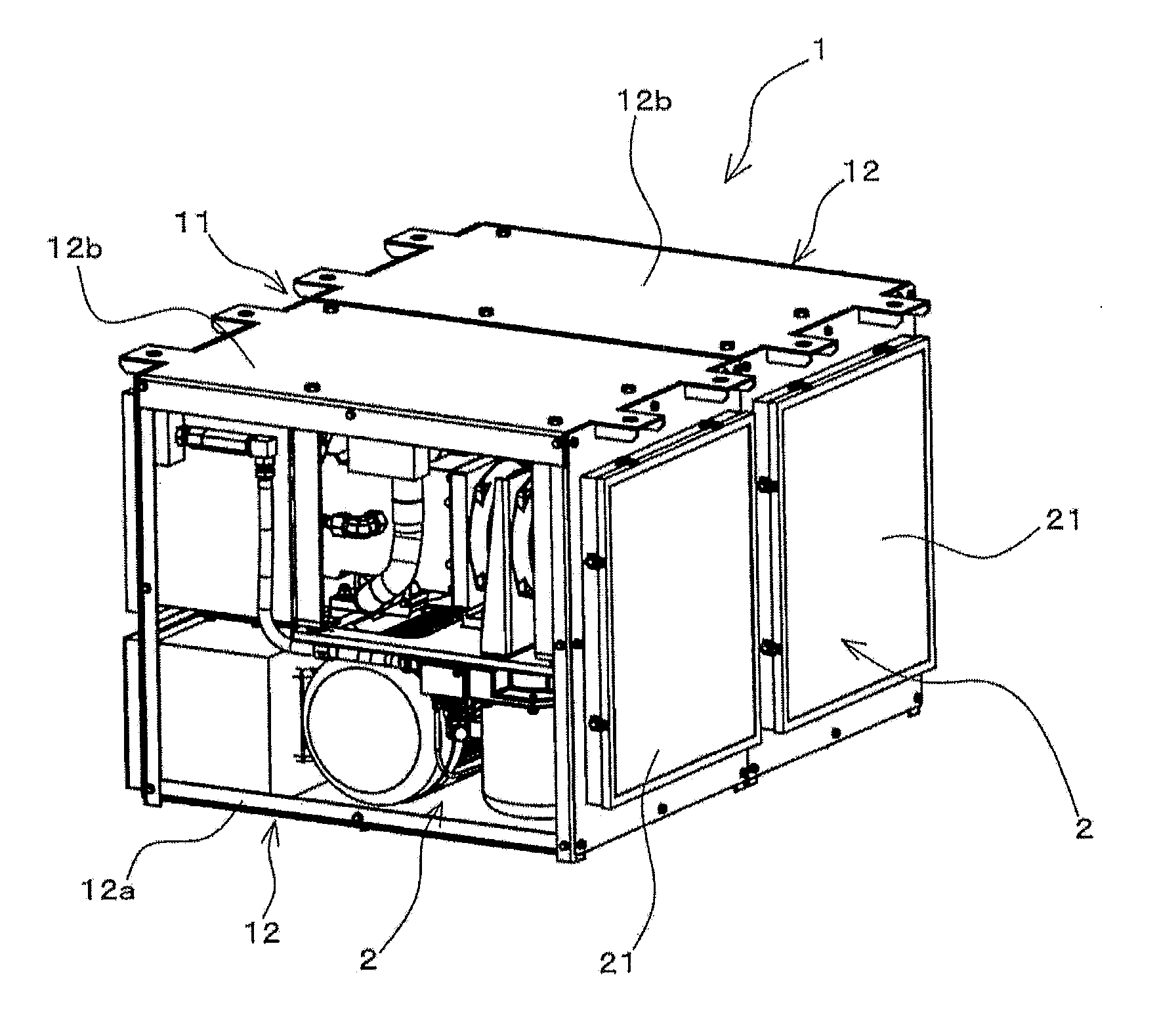
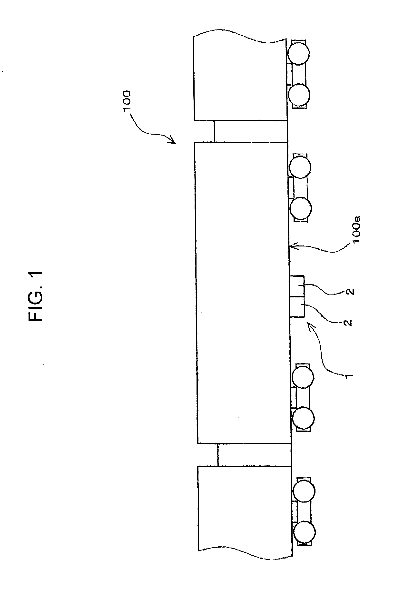
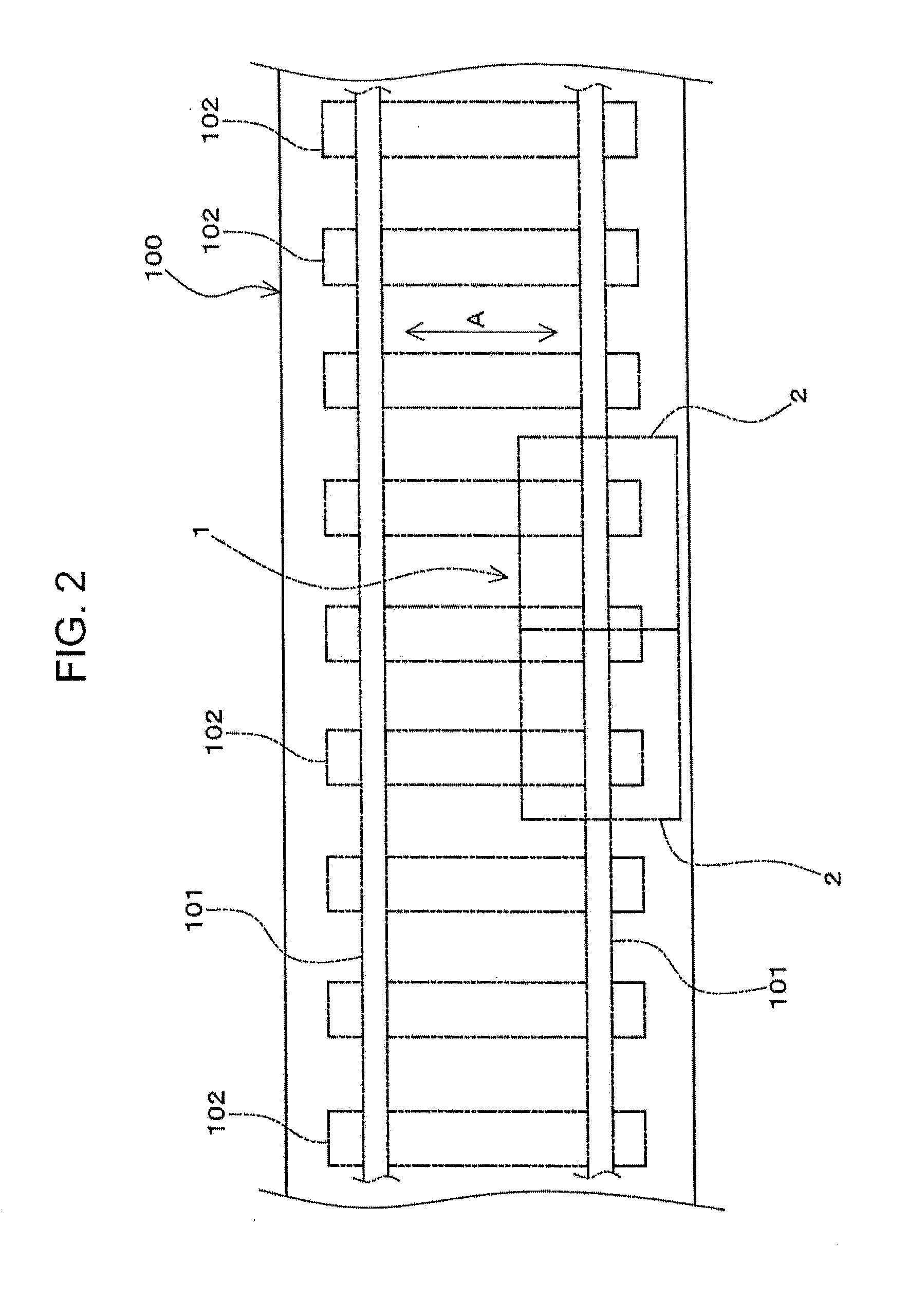
[0020]FIG. 1 is a diagram showing a state where an air compression apparatus for vehicle 1 and air compressor units for vehicle 2 according to one embodiment of the present invention are installed on a vehicle 100 configured as a railway vehicle. FIG. 2 is a plan view diagrammatically showing an installation position of the air compression apparatus for vehicle 1 and the air compressor units for vehicle 2 on the vehicle 100.

[0021]As shown in FIGS. 1 ad 2, the air compression apparatus for vehicle 1 includes a plurality of air compressor units for vehicle 2. The air compressor unit for vehicle 2 of this embodiment is also configu...


PUM


Abstract

An air compressor unit for vehicle (2) includes an air compressor (13) for compressing sucked air, an electric motor (14) for driving the air compressor (13), an after-cooler (17) for cooling compressed air generated in the air compressor (13) and an after-cooler cooling fan (18) for generating cooling air for the after-cooler (17) by being driven by a drive force of the electric motor (14). The air compressor (13) and the electric motor (14) are arranged one above the other.

Description

TECHNICAL FIELD [0001]The present invention relates to an air compressor unit for vehicle to be mounted on a vehicle.BACKGROUND ART [0002]For example, a device mounted on a vehicle to generate compressed air to be used in the vehicle is known as disclosed in Japanese Utility Model Registration No. 3150077. The device disclosed in Japanese Utility Model Registration No. 3150077 includes a plurality of air compressors and a plurality of drive motors. Each air compressor is driven by each drive motor. Each air compressor is coupled in series to the corresponding drive motor. Note that each air compressor is configured as a scroll air compressor.[0003]In the device disclosed in Japanese Utility Model Registration No. 3150077, the air compressors and the drive motors are coupled in series. Thus, a dimension of an air compressor unit including the air compressors and the drive motors becomes long. Then, an installation area required in mounting and installing this air compressor unit on a...

Claims


Application Information

Patent Timeline
Patent Type & Authority Applications(United States)
IPC IPC(8): B61D27/00
CPCB61D27/0072F01C21/007F04C23/005F04C23/02F04C29/04F04C2230/60F04C18/0207
Inventor MIZUFUNE, TORUKUROMITSU, MASARUTAKAHASHI, AKIRAMIYAUCHI, TATSUO
Owner NABLESCO CORP
Why Eureka
Try Eureka