Connecting rod for an impact member of an impact tool

Inactive Publication Date: 2015-11-26
CENTRIFUGE INDAL
View PDF19 Cites 3 Cited by
  • Summary
  • Abstract
  • Description
  • Claims
  • Application Information

AI Technical Summary

Benefits of technology

[0007]The primary object of the present invention is to provide a connecting rod for an impact member of an impact tool. The connecting rod is convenient and fast for assembling/disassembling with the different impact

Problems solved by technology

Especially in some works that the impact tools are unachievable, such that a small impacting force is needed to apply on a work area while the impact tools are unable to provide or the impact tools are unable to b

Method used


Image

  • Connecting rod for an impact member of an impact tool
  • Connecting rod for an impact member of an impact tool
  • Connecting rod for an impact member of an impact tool

Examples


Example

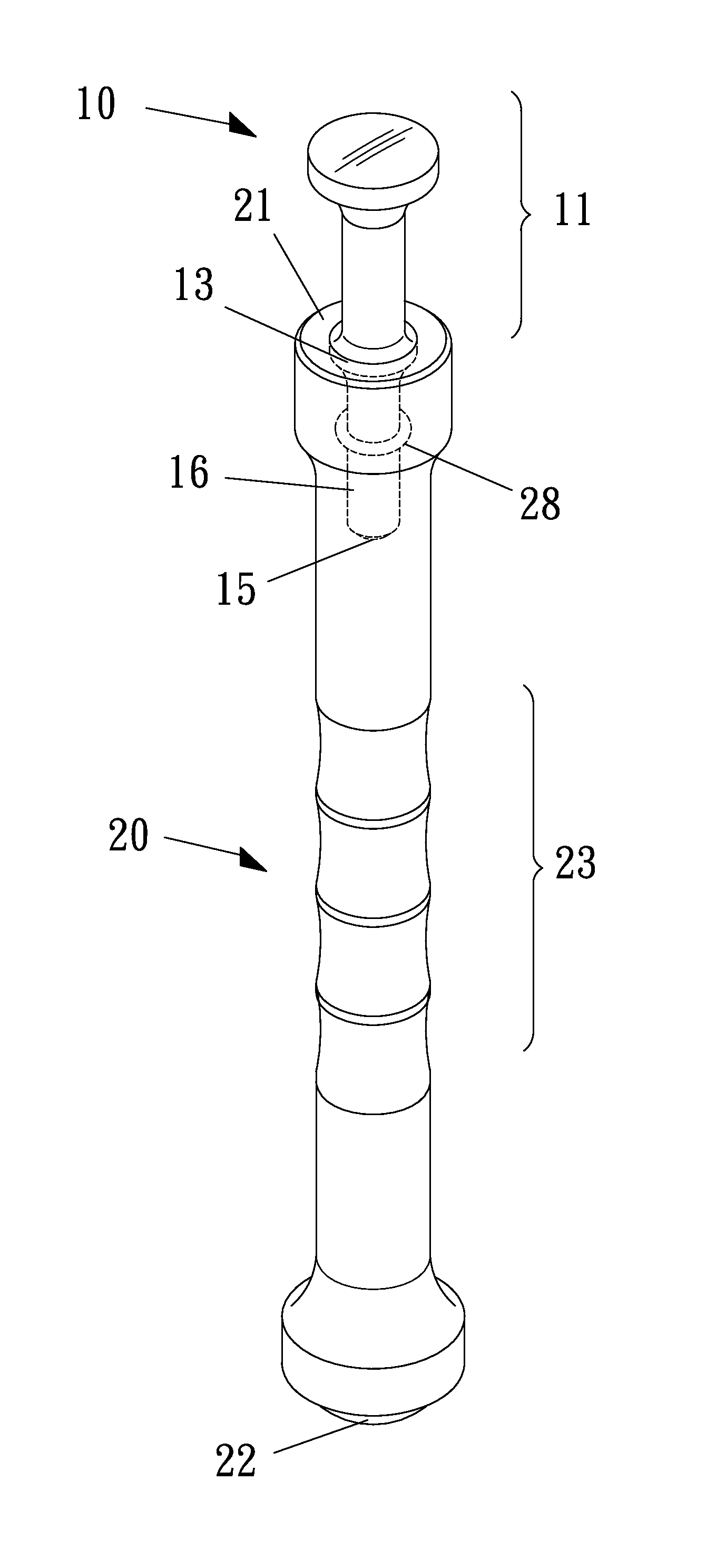
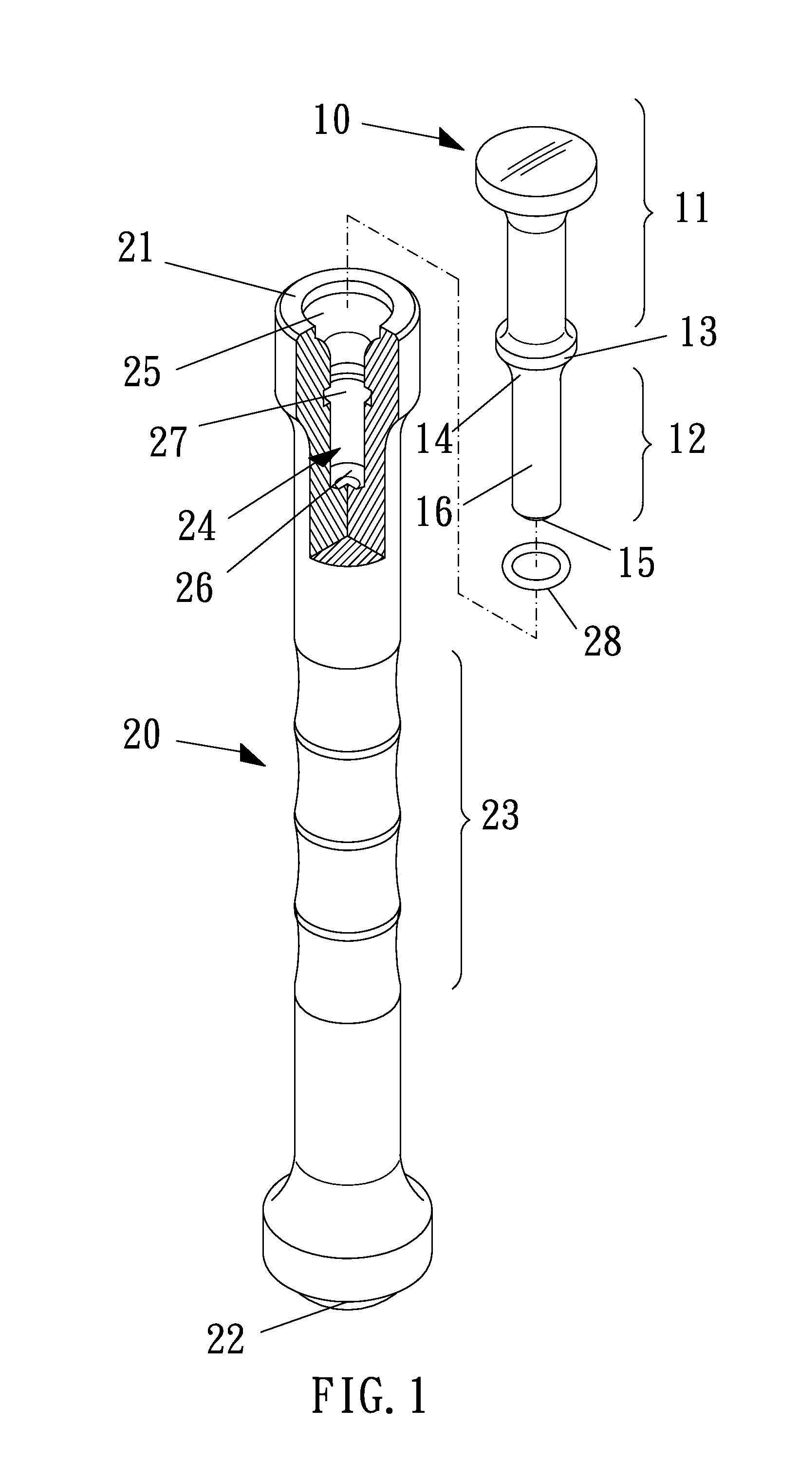
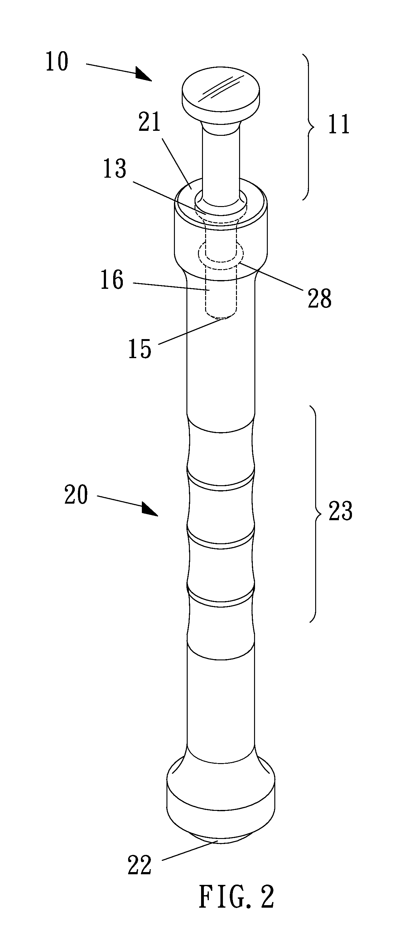
[0014]Referring to FIGS. 1-2, it shows a connecting rod in accordance with a first embodiment of the present invention. The impact member 10 includes axially opposing impacting portion 11 and connecting portion 12 and a radial flange 13 locating between the impacting portion 11 and the connecting portion 12, and the radial flange 13 includes a first abutting surface 14 facing the connecting portion 12. Practically, the impact member 10 has a variety of different shapes. The impacting portion 11 is such as flat-shaped, sharp-shaped or camber-shaped. The connecting portion 12 is such as a circumferential surface of a cylinder or a polygonal pillar and for connecting with the impact tool or the connecting rod. In the present embodiment, the connecting portion 12 is the circumferential surface of a cylinder. The impacting portion 11 and the connecting portion 12 have a same axial direction.

[0015]The impact member 10 is insertable into the impact tool and detachably assembled to the impa...


PUM

PropertyMeasurementUnit
Shapeaaaaaaaaaa
Elasticityaaaaaaaaaa

Abstract

A connecting rod for an impact member of an impact tool is provided. The impact member comprises axially opposing impacting portion and connecting portion and a radial flange locating between the impacting portion and the connecting portion. The radial flange includes a first abutting surface facing the connecting portion. The impact member is insertable into the impact tool and detachably assembled through blocking the radial flange by the impact tool. The connecting rod includes a rod body. The rod body includes receiving end surface and impacting end surface, and a holding portion between the receiving end surface and the impacting end surface. The receiving end surface is recessed to form an assembling slot. The assembling slot includes a second abutting surface disposed circumferentially. When the connecting portion is inserted in the assembling slot, the first abutting surface abuts against the second abutting surface.

Description

BACKGROUND OF THE INVENTION[0001]1. Field of the Invention[0002]The present invention relates to a connecting rod, and more particularly to a connecting rod for an impact member of an impact tool.[0003]2. Description of the Prior Art[0004]Impact tools are quite common and applied in various industries, such as mobile industry, building construction or road maintenance. The impact tools are convenient for equipping with different impact members to work and able to convert a compressive air source into an impacting force effectively. And the impact tools also provide the big impacting force for large constructions and improve the working efficiency.[0005]However, in some practical construction works, it is necessary to use a hand tool and operate by hand. Especially in some works that the impact tools are unachievable, such that a small impacting force is needed to apply on a work area while the impact tools are unable to provide or the impact tools are unable to be applied because of...

Claims


Application Information

Patent Timeline
IPC IPC(8): B25D1/14B25B33/00
CPCB25B33/00B25D1/14B25D3/00B25D2250/111B25D2250/321B25D2250/345
Inventor CHEN, BING-SHENG
Owner CENTRIFUGE INDAL
Why Eureka
Try Eureka