Up-Inclined Coveyor-Driving Fabric Dyeing Machine

a fabric dyeing machine and inclination technology, applied in the direction of washing machine with receptacles, liquid/gas/vapor textile treatment, propelled fabric liquid/gas/vapor treatment, etc., can solve the problems of difficult control of circulation, prone to entanglement, different cycle time of circulation, etc., to eliminate the problem of consuming a large amount of dye liquid, small capacity, and easy to use

Inactive Publication Date: 2015-11-26
CHANG
View PDF8 Cites 8 Cited by
  • Summary
  • Abstract
  • Description
  • Claims
  • Application Information

AI Technical Summary

Benefits of technology

[0008]An object of the present invention is to provide a dyeing machine that greatly reduces the amount of the dye liquid (namely the amount of water) used as compared to a conventional fabric dyeing machine so as to further reduce the cost of dyeing fabrics and to promote the effect of environmental protection.
[0009]Another object of the present invention is to provide a dyeing machine that reduces the height distance between a fabric guide roller and a conveyor device in order to allow the fabric that is driven by the fabric guide roller and the conveyor device to subject to a decreased stretching force and thus protecting the fabric from damage of the construction and characteristics thereof.
[0010]A feature of the present invention is that a liquid storage tank is mounted to a bottom of a rear end of a fabric dyeing machine so that the dye liquid contained in the machine body, after dyeing a fabric within a nozzle and a dyeing tube, can be all collected and accumulated in the liquid storage tank except the fraction of the dye liquid that is contained in the fabric, allowing a pump to directly suck the dye liquid from the liquid storage tank and pumping it through a heat exchanger to be conveyed to the nozzle to complete a dyeing cycle. Further, since the pump is allowed to directly suck the dye liquid from the rear end of the machine body, the water consumption for the dye liquid to flow from a rear end of the machine body to the front end can be eliminated. Further, a liquid storage tank, which receives and preserves the dye liquid therein, has a planar surface area that is smaller than the dyeing bath so that the liquid level can be heightened, facilitating the pumping operation of the pump, preventing vacuum induced through evacuation, reducing the amount of liquid required for the circulation, thereby greatly reducing the amount of dye liquid used, reducing fabric dyeing expense, and being more environmentally conservative.
[0011]Another feature of the present invention is that the bottom of the rear end of the machine body of the dyeing machine is set at a lower position, while the front end is set a higher position to show an up-inclined configuration so that besides reducing the height of the fabric guide roller inside the machine body, the distance between the fabric guide miler and the conveyor device is also shortened to reduce the stretching force applied to moving the fabric by the fabric guide roller and the own weight of the wetting fabric.
[0013]In a preferred embodiment, the present invention comprises a filter mounted in the liquid storage tank to filter off the fluff from the fabric or impurities, which entrain the dye liquid, in order to eliminate the water consumption for installation of an additional filtration tank.
[0014]The present invention provides a liquid storage tank that is arranged at the rear end of the machine body, has a relatively small capacity, but provides a liquid level difference that is relatively higher than the machine body to serve as a container for collecting and accumulating the dye liquid, so as to eliminate the problem of consuming a great amount of dye liquid. Further, the up-inclined machine body of the dyeing machine also helps reduce the height of the fabric guide roller that is located at a high position and thus shortening the distance between the high-position fabric guide roller and the low-position conveyor device, thereby reducing the stretching force and the own weight of the fabric that the fabric guide roller applies to move the fabric.

Problems solved by technology

(1) The fabric is moved (forward) by being driven by the dye liquid with the fabric immersed in or floating on the dye liquid, so that the liquor ratio must be extremely large, requiring a great amount of dye liquid to enable circulation and movement of the fabric; the amount of water used is relatively great; the fabric may move irregularly with the dye liquid, making it hard to control the circulation and susceptible to entangling; and the circulation speed of the fabric is unstable and variable, making the cycle time of circulation differ greatly.
(2) Although the fabric is afloat with the flotage of the dye liquid, most of the fabric still sinks down to the bottom of dyeing bath, so that the fabric may get pilling and scraped during the conveyance thereof due to abrasion between the fabric and the wall of the dye bath and the fabric may be further damaged in respect of the construction and characteristics thereof due to the stretching forces induced in driving the fabric.
(3) The dye liquid that is applied to dye the fabric and then falls down in the rear end of the dye tube must flows from the rear end of the machine body to the front end that is at a relative lower position and the dye liquid must be then drawn and pumped by a pump to a nozzle for further driving the fabric to circulate, so that a great amount of liquid is needed in the dye bath of the machine body and thus a great consumption of the dye liquid may result.
(4) Since the fabric is conveyed with the dye liquid, in addition to the great consumption of water, the liquor ratio may get varying greatly when the actual loading of fabric applied is less than the minimal loading capacity, whereby, besides the great consumption of water, other shortcomings, such as poor reproductivity, batch deviation, and color mismatching, may occur.
Further, since the rear end of the machine body of the conventional dyeing machine is set at a location higher than the front end, the fabric guide roller must be set at a higher location inside the machine body, making the stretching force or tension force that the fabric guide roller applies to the fabric or the fabric self weight increased, leading to the problem of damaging the construction and characteristics of the fabric.

Method used


Image

  • Up-Inclined Coveyor-Driving Fabric Dyeing Machine
  • Up-Inclined Coveyor-Driving Fabric Dyeing Machine
  • Up-Inclined Coveyor-Driving Fabric Dyeing Machine

Examples


Embodiment Construction

[0019]The following descriptions are exemplary embodiments only, and are not intended to limit the scope, applicability or configuration of the invention in any way. Rather, the following description provides a convenient illustration for implementing exemplary embodiments of the invention. Various changes to the described embodiments may be made in the function and arrangement of the elements described without departing from the scope of the invention as set forth in the appended claims.

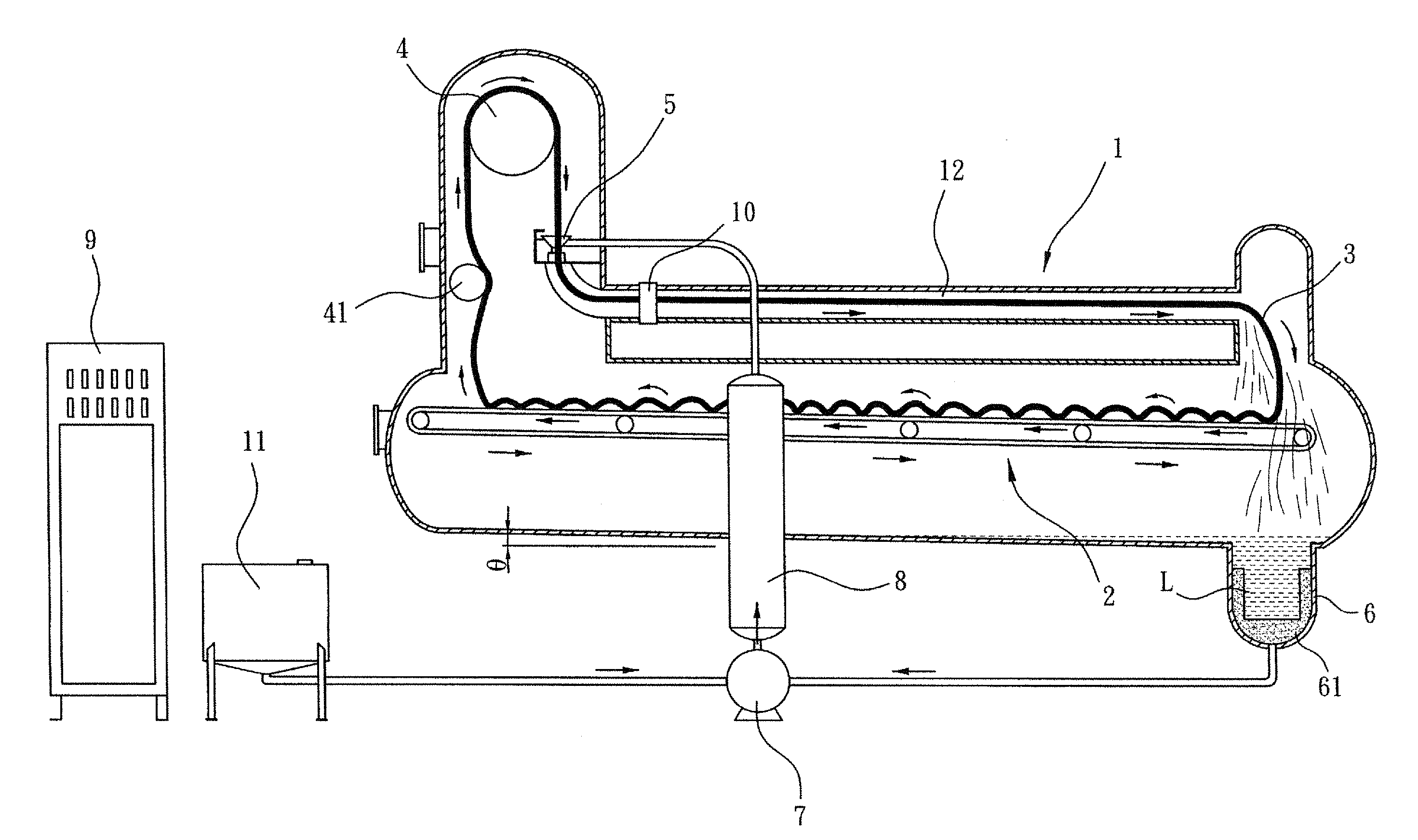
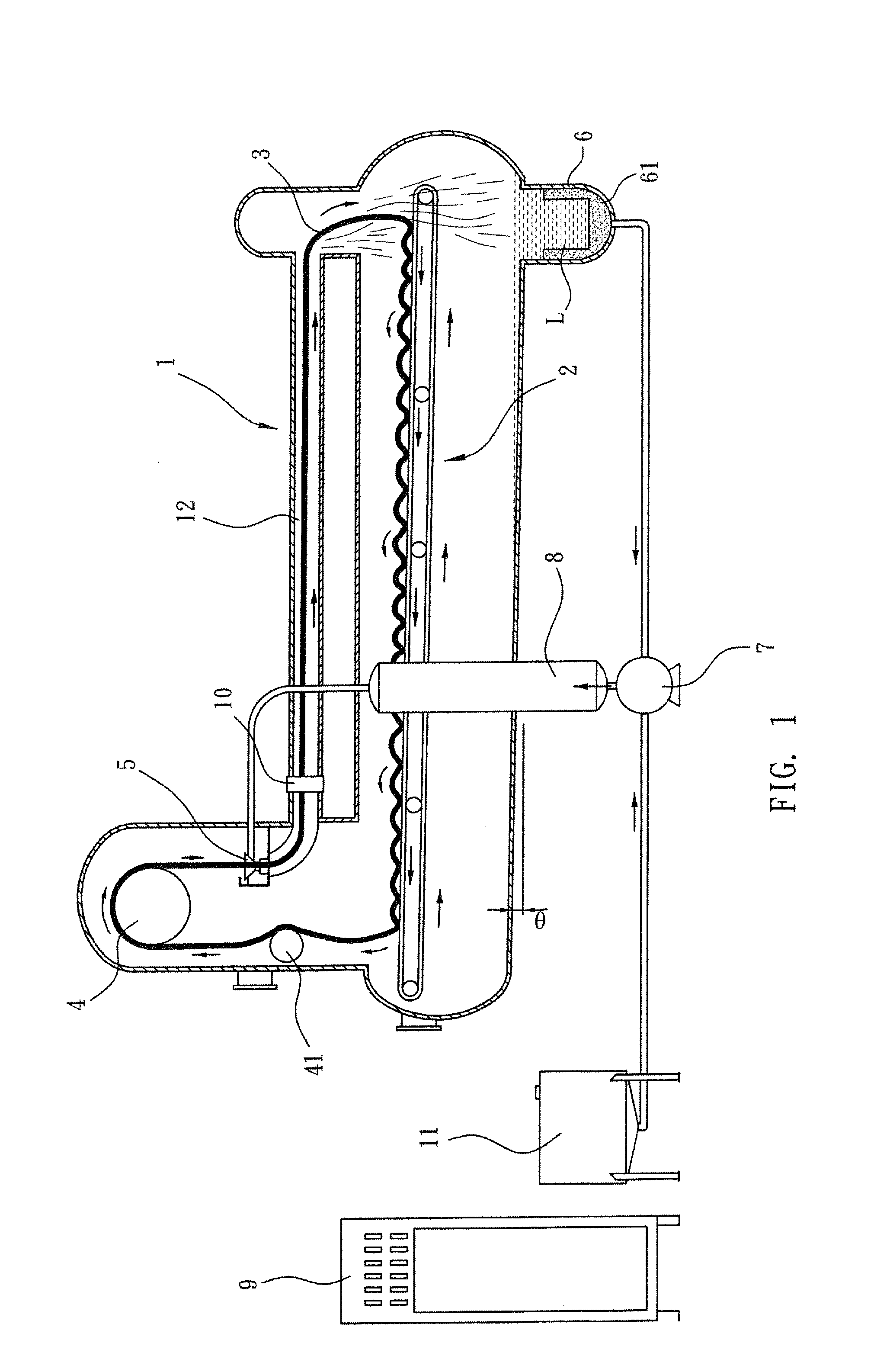
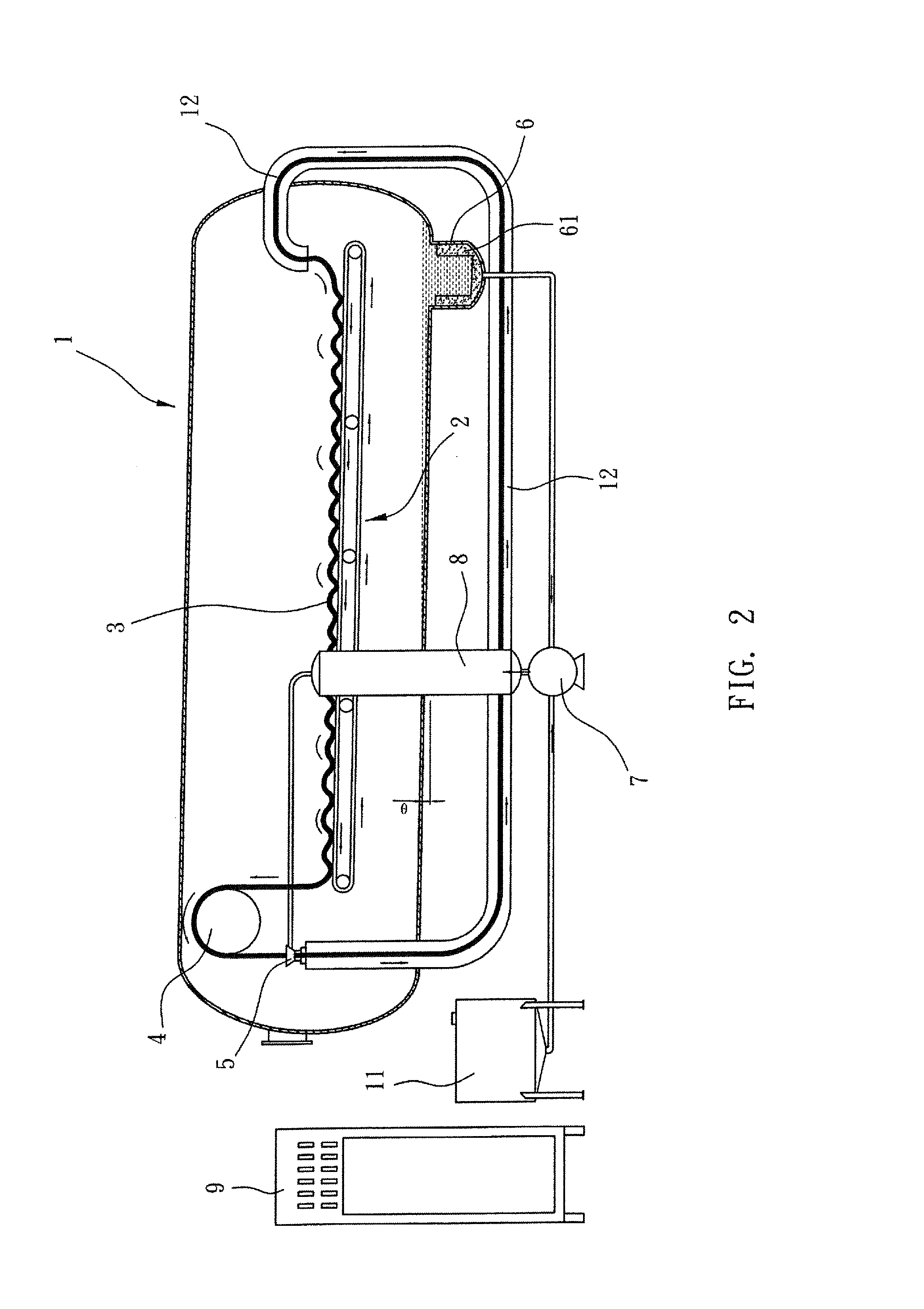
[0020]As shown in FIG. 1, the present invention provides an up-inclined conveyor-driving fabric dyeing machine, which comprises a dyeing tube 12 that is arranged at the top portion of a machine body 1 to in a horizontal or slightly inclined configuration to allow a fabric to pass therethrough. Mounted inside the machine body 1 at high locations are a nozzle 5 and a fabric guide roller 4. An idler 41 is mounted below the fabric guide roller 4. The machine body 1 is set in an inclined configuration wi...


PUM


Abstract

An up-inclined conveyor-driving fabric dyeing machine includes a machine body that is arranged in a front-high-and-rear-low up-inclined configuration. A liquid storage tank is mounted to a bottom of a rear end of the machine body to receive dye liquid falling down from a rear end of a dyeing tube. Thus, the amount of the dye liquid used can be greatly reduced. Further, with such an up-inclined configuration of the dyeing machine, the dyeing tube can be arranged in a horizontal or slightly inclined manner to reduce the heights of a fabric guide roller and the conveyor and thus reduce the distance between the fabric guide roller and the conveyor device, thereby reducing the stretching force and tensile force applied to the fabric during the dyeing process.

Description

(A) TECHNICAL FIELD OF THE INVENTION[0001]The present invention generally relates to a dyeing machine for dyeing fabrics, and more particularly to a dyeing machine that remarkably reduces water consumption so as to reduce the use of stream, chemical agents, and dye stuff, making the cost of fabric dyeing more economic and better meeting the need for environmental conservation, and also helping protect the fabric from being damaged by excessive stretching forces during the dyeing process.(B) DESCRIPTION OF THE PRIOR ART[0002]In a conventional fabric dyeing machine, when a fabric is circulated and thus dyed in a machine body thereof, since the fabric, in moving frontward from a rear end of the dyeing machine, is assisted by the flotation of the dye liquid and the driving force of the dye liquid, the rear end of the machine body is generally designed to be horizontal or relatively high, while the front end is made lower so as to show a front-low-rear-high inclined configuration. Thus, ...

Claims


Application Information

Patent Timeline
Patent Type & Authority Applications(United States)
IPC IPC(8): D06B3/10D06B3/34
CPCD06B3/34D06B3/10D06B3/28D06B23/14
Inventor CHANG
Owner CHANG
Why Eureka
Try Eureka