Ball joint

a ball joint and ball bearing technology, applied in the direction of shafts and bearings, pivots, couplings, etc., can solve the problems of component malfunction, failure to perform the function of the component, and inability to accept the steering degree, so as to reduce manufacturing costs

Active Publication Date: 2015-11-26
ZF FRIEDRICHSHAFEN AG
View PDF2 Cites 8 Cited by
  • Summary
  • Abstract
  • Description
  • Claims
  • Application Information

AI Technical Summary

Benefits of technology

[0008]For this reason, the object of the present invention is to provide a ball joint or, respectively, a ball socket, which counteracts the above-mentioned disadvantages, and which better ensures that the ball socket has a high thermal and mechanical load capacity. The improvement of the ball joint should be ensured in a structurally simple manner, and thus, the ball joints should be cost-effective to produce.

Problems solved by technology

Over the service life or, respectively, lifespan of a ball joint, wear may occur as a result of friction or thermally induced creep of the material of the ball socket within the ball joint, for example, if the ball joint is used to connect at least two chassis components in the chassis of a motor vehicle.
The wear may make itself felt through noises as a result of play within the ball joint and may lead to impermissible degree of play in the steering.
In extreme cases, the component will malfunction and fail to perform its function.

Method used


Image

  • Ball joint
  • Ball joint

Examples


Embodiment Construction

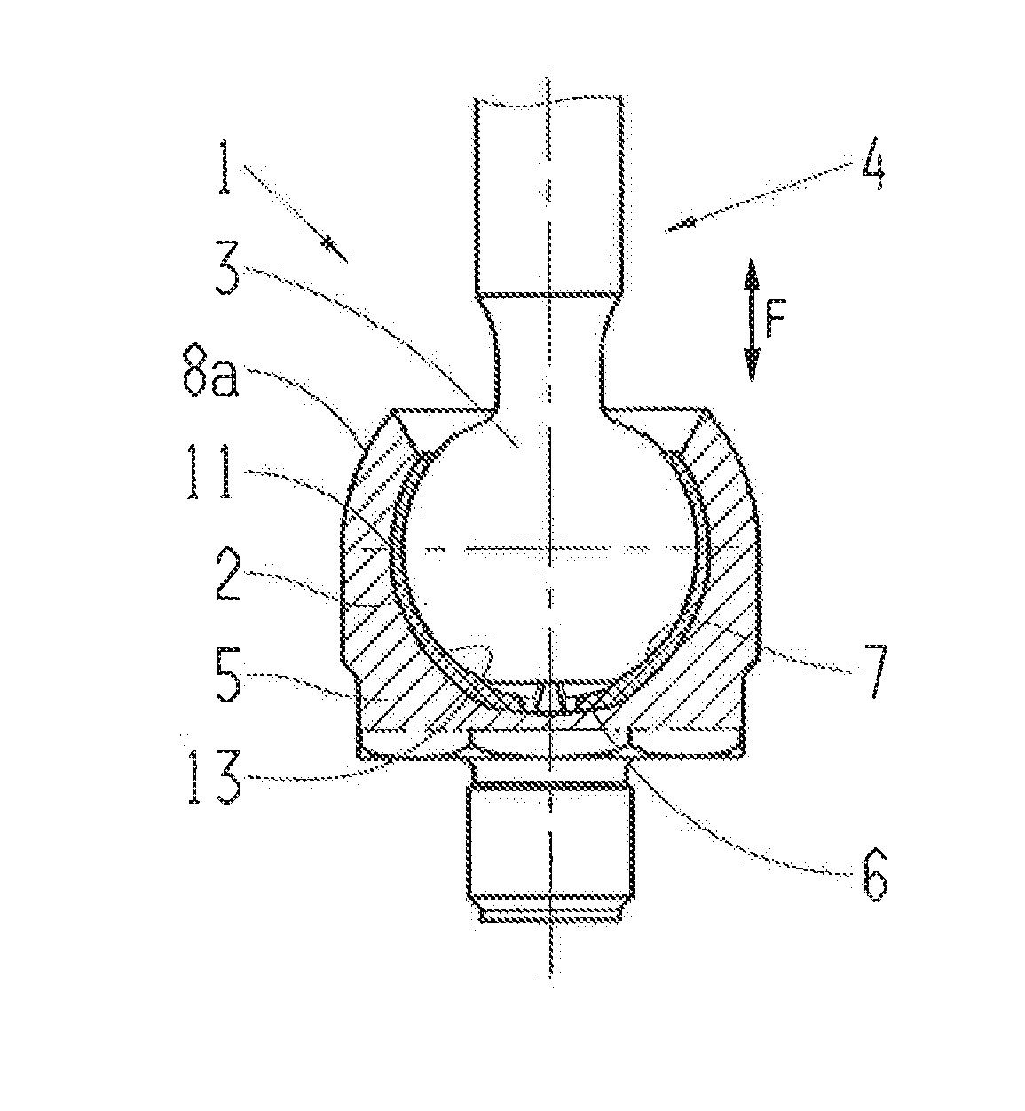
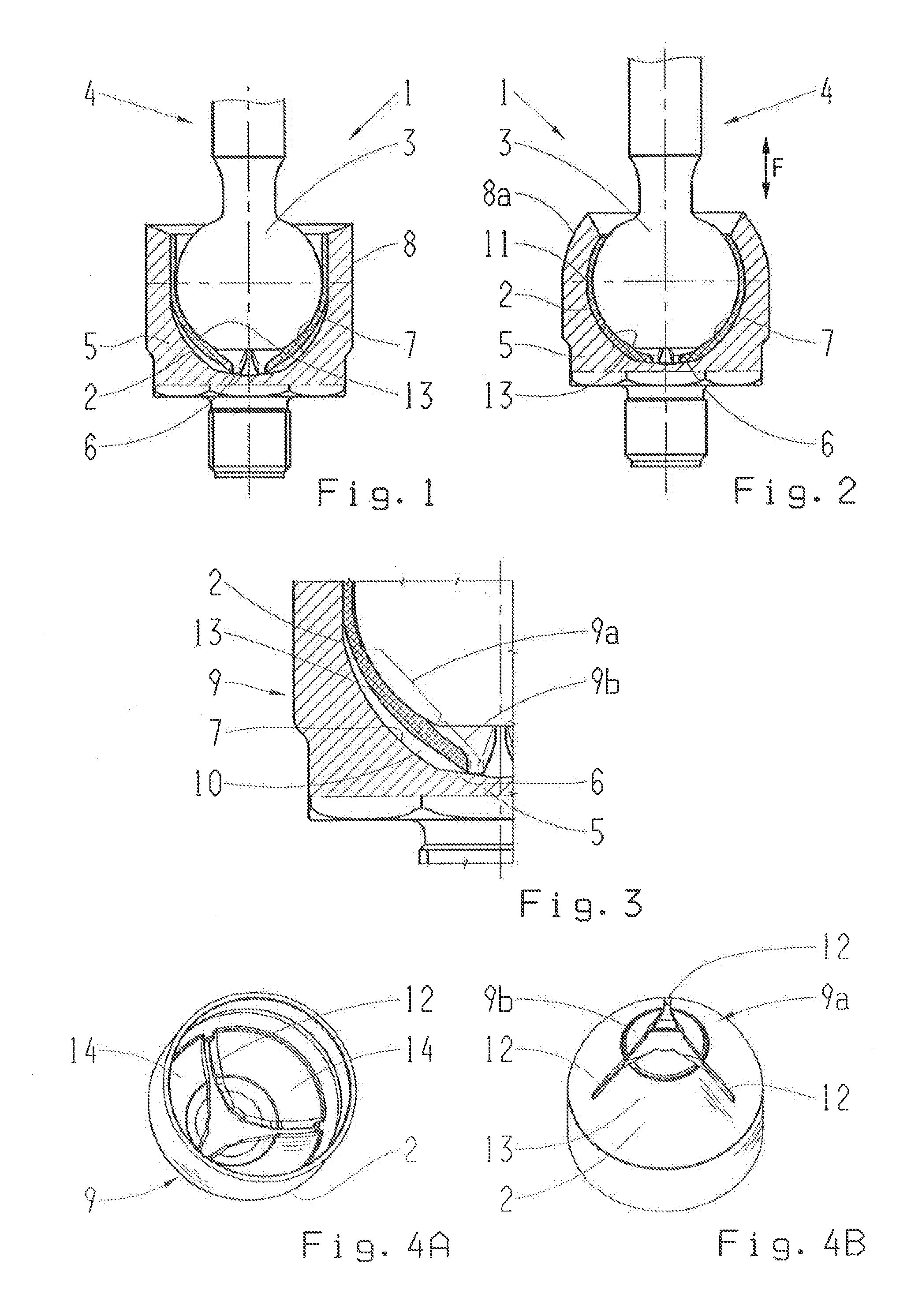
[0034]FIG. 1 shows a sectional view of a ball joint 1 according to an embodiment of the invention, designed as an axial joint, in a preassembled state. As is evident here, the ball joint comprises a ball socket 2, in which a joint ball 3 of a ball stud 4 is disposed. The ball socket 2, in turn, is enclosed in a housing 5. As such, in the pre-assembled state, the ball socket 2 is resting on the spring element 13, which will be described in greater detail in conjunction with FIGS. 4A and 4B, on the housing base 6.

[0035]FIG. 2 again shows a sectional view of the joint assembly 1 depicted in FIG. 1, in an assembled state. As indicated here, the main direction of stress, which is indicated by the double arrow with the reference character F, extends axially, in the traction and compression direction. In the assembled state, the ball socket 2 rests completely against the supporting regions, that is, on the inner wall 7 of the housing 5 and on the joint ball. The spring element 13 (see FIGS...


PUM


Abstract

A ball joint, in particular, an axial joint, having a ball stud, which is enclosed in a ball socket. The ball socket is enclosed in a joint housing and is integrally formed having at least one spring element in a region of the ball socket that faces away from the opening of the joint housing. The spring element has discontinuities, in particular in the form of slots, so that wear compensation is created by the spring element within the ball joint.

Description

[0001]This application is a National Stage completion of PCT / EP2013 / 076757 filed Dec. 16, 2013, which claims priority from German patent application serial no. 10 2013 200 586.5 filed Jan. 16, 2013 and German patent application serial no. 10 2013 200 510.5 filed Jan. 15, 2013.FIELD OF THE INVENTION[0002]The invention relates to a ball joint, in particular, an axial joint, a ball socket as well as a method of manufacturing the ball socket.BACKGROUND OF THE INVENTION[0003]Ball joints are frequently used in the prior art in motor vehicles, where the joints are exposed to high loads. Axial and radial joints are known in this connection. As is known, the designation of radial or axial joint refers to the main direction of stress of the ball joint in question. Thus, axial joints are primarily subjected to tensile and / or compressive loads parallel to the longitudinal axis thereof. Radial joints, on the other hand, are primarily subjected to loads transverse to the longitudinal axis thereof...

Claims


Application Information

Patent Timeline
Patent Type & Authority Applications(United States)
IPC IPC(8): F16C11/06
CPCY10T403/32811F16C11/0652F16C11/0647F16C11/0685F16C11/086Y10T403/32713Y10T403/32737F16C11/0638
Inventor GRABER, JURGENUNGRUH, RAINERFRICKE, CORD
Owner ZF FRIEDRICHSHAFEN AG
Why Eureka
Try Eureka