
System and Method for a Self-system Analysis in a Wireless Power Transmission Network

a wireless power transmission network and self-system analysis technology, applied in the field of electronic transmitters, can solve the problems of inoperable electronic devices during charging, burden on users, tedious activity,

Active Publication Date: 2015-11-26
ENERGOUS CORPORATION
View PDF2 Cites 230 Cited by
  • Summary
  • Abstract
  • Description
  • Claims
  • Application Information

AI Technical Summary

Benefits of technology

The present patent describes a system and method for self-monitoring and analysis in a wireless power transmission network. The system includes multiple wireless power transmitter managers and receivers, and each manager has a device database that stores information about all system devices. The system also includes a business cloud and service provider cloud for sharing device database information. The wireless power transmitter managers can self-monitor the network, detect failures, analyze the problem, and make recommendations for enhancements or corrections to the system. The technical effect of this patent is to enable self-monitoring and analysis in a wireless power transmission network, allowing for timely detection and resolution of problems.

Problems solved by technology

Such an activity may be tedious and may represent a burden to users.
In addition, users may have to find available power sources to connect to.
However, such an activity may render electronic devices inoperable during charging.
Nevertheless, such a solution may still require that electronic devices may have to be placed in a specific place for powering.
Thus, electronic devices during charging may not be portable.
However, when a device fails in the system, the power transfer to an electronic device may be interrupted.
Different causes may exist for a failure, including a loss of power, a failure in the hardware or software of a wireless power transmitter manager, overload of the wireless power transmitter manager, and malfunction in a wireless power receiver, among others.

Method used


Image

  • System and Method for a Self-system Analysis in a Wireless Power Transmission Network
  • System and Method for a Self-system Analysis in a Wireless Power Transmission Network
  • System and Method for a Self-system Analysis in a Wireless Power Transmission Network

Examples


examples

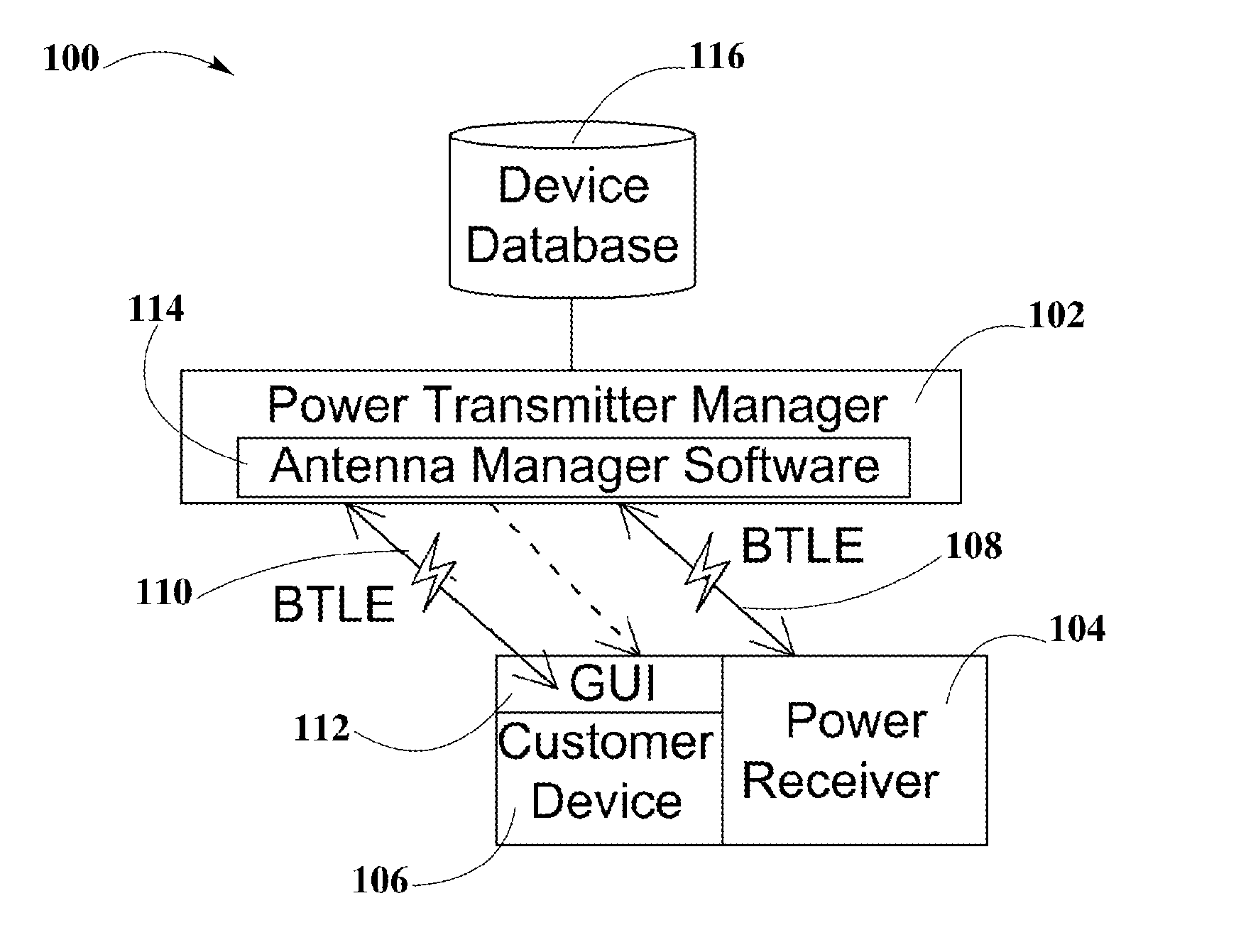
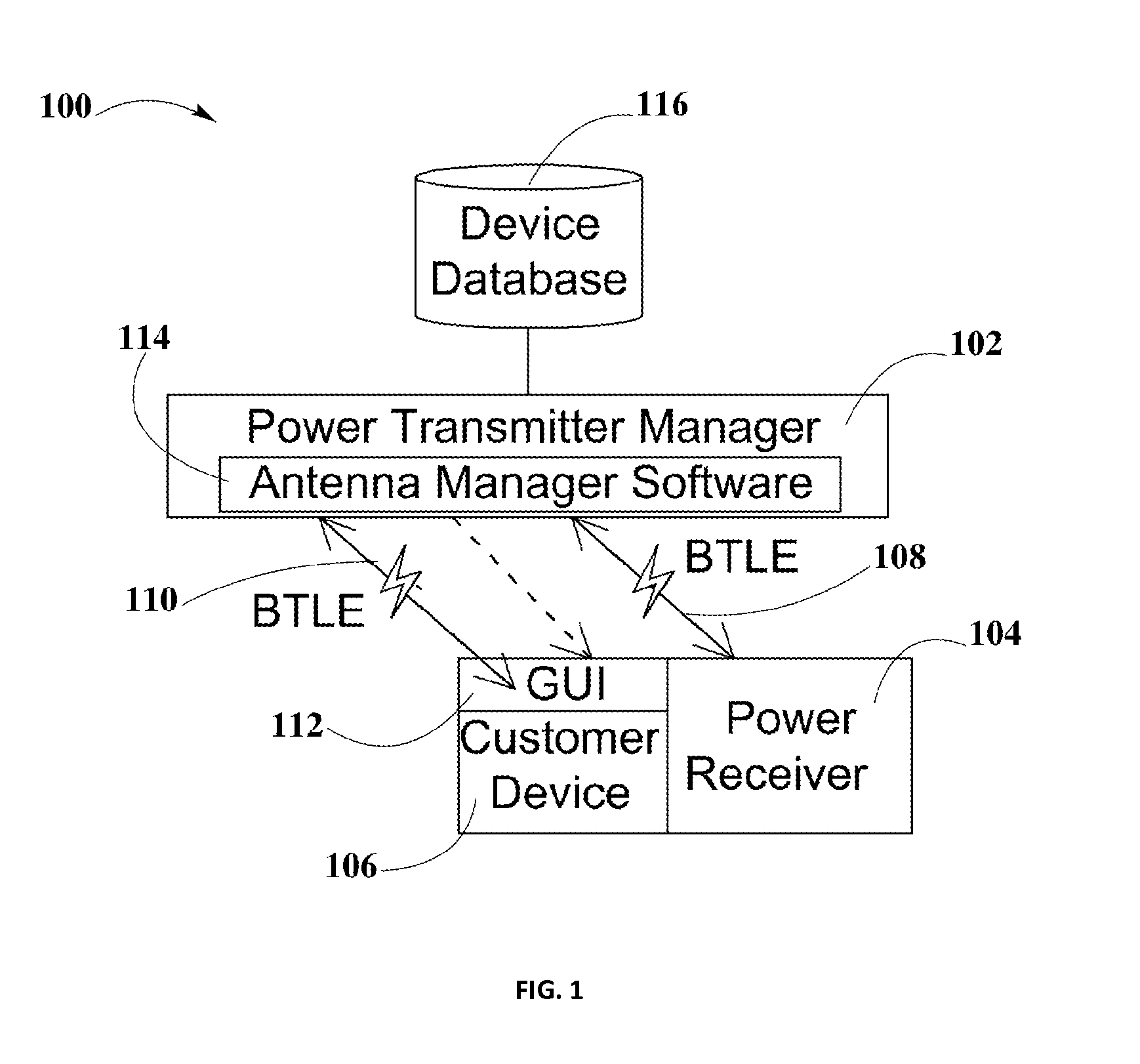
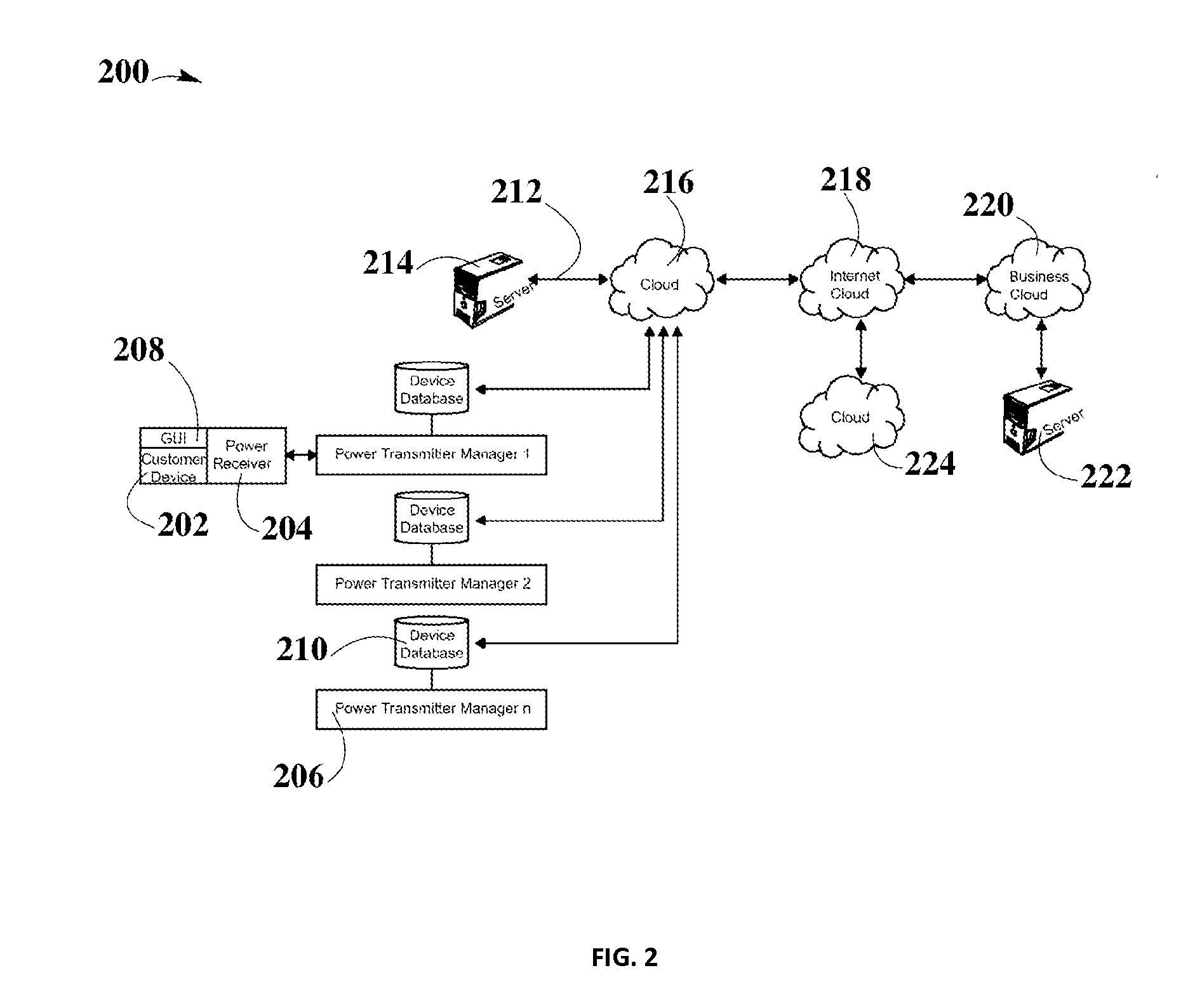
[0075]Example #1 is a wireless power transmission network with components similar to those described in FIG. 2. The wireless power transmission network may be working in a school, where student may charge their electronic devices wirelessly. A student may be charging his cellphone in the science classroom. The student starts moving because he needs to take another class in a different classroom. The student arrives to the computer classroom, but he is unable to continue charging his cellphone. At the same time that the student arrives to the computer classroom the wireless power transmitter manager near to the computer classroom exceeds the amount of electronic devices to be powered. Wireless power transmitter manager may detect a failure in his performance and may start analyzing the reason performance was affected. Wireless power transmitter manager may find that an overload was the reason of its performance being affected. After the analysis is completed, a recommendation may be ...


PUM


Abstract

A system and method for a self-system analysis in a wireless power transmission network is disclosed. According to some aspects of this disclosure a wireless power transmission network may include one or more wireless power transmitter managers, one or more wireless power receivers, servers, and clouds within a local network to provide wireless power transfer to electronic devices. Wireless power devices in the network may establish, but is not limited to a WiFi connection to share information among all the wireless power devices in the system. Wireless power transmitter managers may monitor everything that happens in the network. If a problem is detected by the wireless power transmitter manager, an analysis of the issue may be done by any device in the network with a copy of the device database. Then a recommendation may be generated for enhancing the system.

Description

CROSS-REFERENCE TO RELATED APPLICATIONS[0001]The present disclosure is related to U.S. non-provisional patent application DWV-3DPF-010 entitled “Methodology for Pocket-forming”; and DWV-3DPF-028 entitled “Methodology for Multiple Pocket-Forming”; DWV-3DPF-015 entitled “Method for 3 Dimensional Pocket-forming”; DWV-3DPF-027 entitled “Receivers for Wireless Power Transmission”; DWV-3DPF-029 entitled “Transmitters for Wireless Power Transmission” invented by Michael Leabman, each of which are incorporated by reference in their entirety herein.BACKGROUND[0002]1. Field of the Disclosure[0003]The present disclosure relates in general to electronic transmitters, and more specifically to a system and method for a self-system analysis in a wireless power transmission network.[0004]2. Background Information[0005]Electronic devices such as laptop computers, smartphones, portable gaming devices, tablets, and so forth may need power for performing their intended functions. This may need having t...

Claims


Application Information

Patent Timeline
IPC IPC(8): H02J17/00
CPCH02J17/00H02J50/80H02J50/20H02J50/40
Inventor BELL, DOUGLASLEABMAN, MICHAEL
Owner ENERGOUS CORPORATION
Learn More