Circuit structure and method for reducing power consumption of device including active module and passive module

Active Publication Date: 2015-11-26
ABB (SCHWEIZ) AG
View PDF7 Cites 0 Cited by
  • Summary
  • Abstract
  • Description
  • Claims
  • Application Information

AI Technical Summary

Benefits of technology

[0031]Compared with the prior art solution, the circuit structures and methods as provided in the embodiments of the pres

Problems solved by technology

However, the parallel redundancy requires a high reliability in module synchronization as well as accuracy of each single module.
Therefore, the parallel redundancy is not only difficult to implement, but also its manufacturing cost will be relatively higher.
However, an output current inside the passive module also increases power consumption of the passive module.
And power consumption of the redundant pas

Method used


Image

  • Circuit structure and method for reducing power consumption of device including active module and passive module
  • Circuit structure and method for reducing power consumption of device including active module and passive module
  • Circuit structure and method for reducing power consumption of device including active module and passive module

Examples


Example

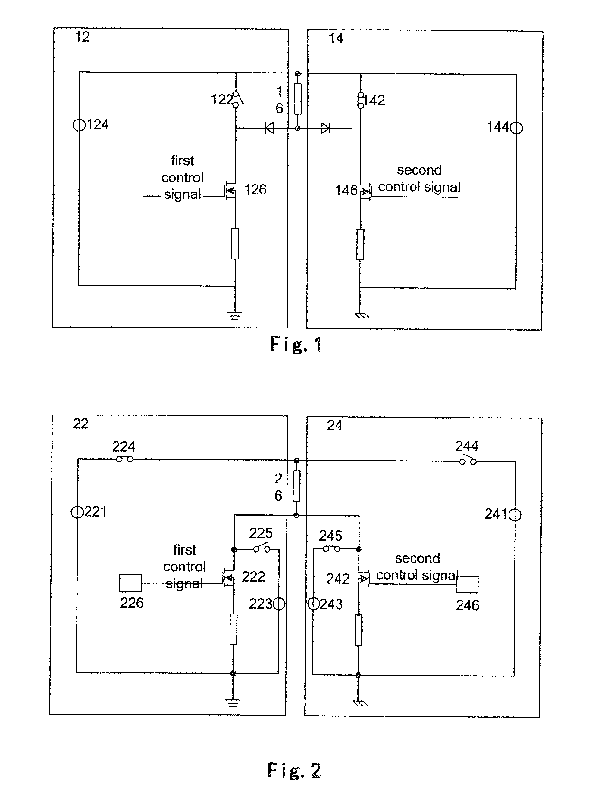
[0044]As shown in FIG. 2, a circuit structure according to the first embodiment comprises an active module 22 and a passive or backup module or 24. In the exemplary embodiments, the active module 22 can comprise a main output voltage 221, which is configured to power a load 26 via a first current control device 222 when the active module 22 is in the active state. When the active module 22 is in the active state, a current passing through the load 26 may be controlled by applying a control signal to a control terminal of the first current control device 222.

[0045]Further, as shown in FIG. 2, the passive module 24 comprises a main output voltage 241, which is configured to power the load 26 via a second current control device 242 when the active module 22 fails, for example, an error is happened in the active module 22. When the passive module 22 is in the active state, a current passing through the load 26 may be controlled by applying a control signal to a control terminal of the s...


PUM


Abstract

Embodiments of the present invention disclose a circuit structure and a method for reducing power consumption of a device including an active module and a passive module. The circuit structure comprises: an active module (22) comprising a main output voltage (221) for powering a load (26) via a first current control device (222) which is configured to control a current passing through the load (26), and an passive module (24) comprising a main output voltage (241) for when the active module (22) fails, powering the load (26) via a second current control device (242) which is configured to control a current passing through the load (26). The passive module (24) further comprises an auxiliary output voltage (243) for when the passive module (24) is in a backup state, powering the second current control device (242) so as to enable the second current control device (242) to be in a switching-on state. Further, the auxiliary output voltage (243) of the passive module (24) is configured to be smaller than the main output voltage (241) of the passive module (24).

Description

TECHNICAL FIELD[0001]Embodiments of the present invention relate to the field of power electronics, and more particularly, relate to a circuit structure and a method for reducing power consumption of a device including an active module and a passive module.BACKGROUND ART[0002]Redundancy is widely used in various process controls which need a higher reliability. Input / output (I / O) redundancy in a discrete controlling system (DCS) provides two modules with identical hardware and firmware structures, namely, one is an active module, and the other is a passive or backup module. As soon as an error is happened in the active module, a switchover from the active module to the passive module will be initiated. Then, an active module will stop working, and the passive module will take over the responsibility to keep the process control running. Redundancy design in the I / O module increases the reliability of the DCS and make sure that an error in the I / O module will not affect the process co...

Claims


Application Information

Patent Timeline
IPC IPC(8): H02M3/335H02M1/00H02M1/32
CPCH02M3/33546G06F1/30G06F1/3206H02J9/061H02M3/1584H02M3/3376H02M1/0006H02M1/325Y02B70/30Y04S20/20G05F1/00G05F1/46G05F1/56
Inventor SHI, HUANLOHBECK, AXEL
Owner ABB (SCHWEIZ) AG
Why Eureka
Try Eureka