Selectively Deployable Rotatable Edge Guide to Support a Cutting Tool During a Sharpening Operation

Active Publication Date: 2015-12-03
DAREX
View PDF4 Cites 0 Cited by
  • Summary
  • Abstract
  • Description
  • Claims
  • Application Information

AI Technical Summary

Benefits of technology

[0006]In related embodiments, the tool sharpener has a base structure which encloses an electric motor. An abrasive medium is supported by the base structure and adapted for rotational movement responsive to the electric motor, the abrasive medium having an abrasive surface extending along a neutral plane. A stationary tool support guide has a guide surface extending along a guide plane at a selected angle with respect to the neutral plane to engage, via sliding contact, a side of the tool during presentation of a cutting edge of the tool against the abrasive surface. A rotatable edge guide adjacent the stationary tool

Problems solved by technology

Cutting tools can become dull

Method used


Image

  • Selectively Deployable Rotatable Edge Guide to Support a Cutting Tool During a Sharpening Operation
  • Selectively Deployable Rotatable Edge Guide to Support a Cutting Tool During a Sharpening Operation
  • Selectively Deployable Rotatable Edge Guide to Support a Cutting Tool During a Sharpening Operation

Examples


Example

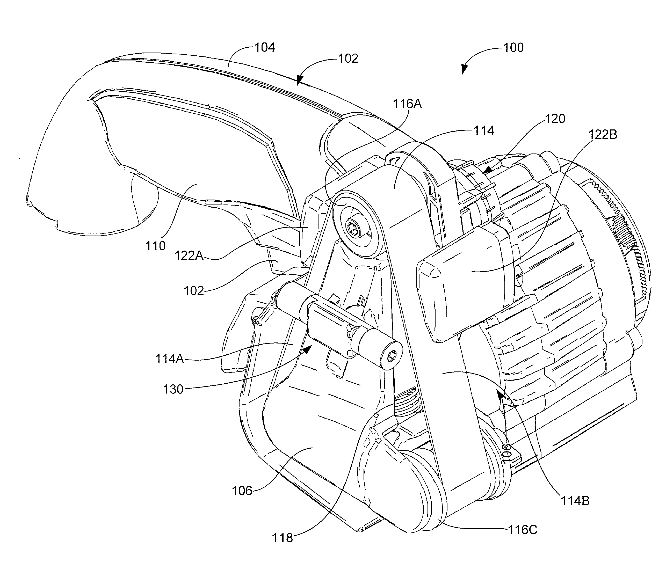
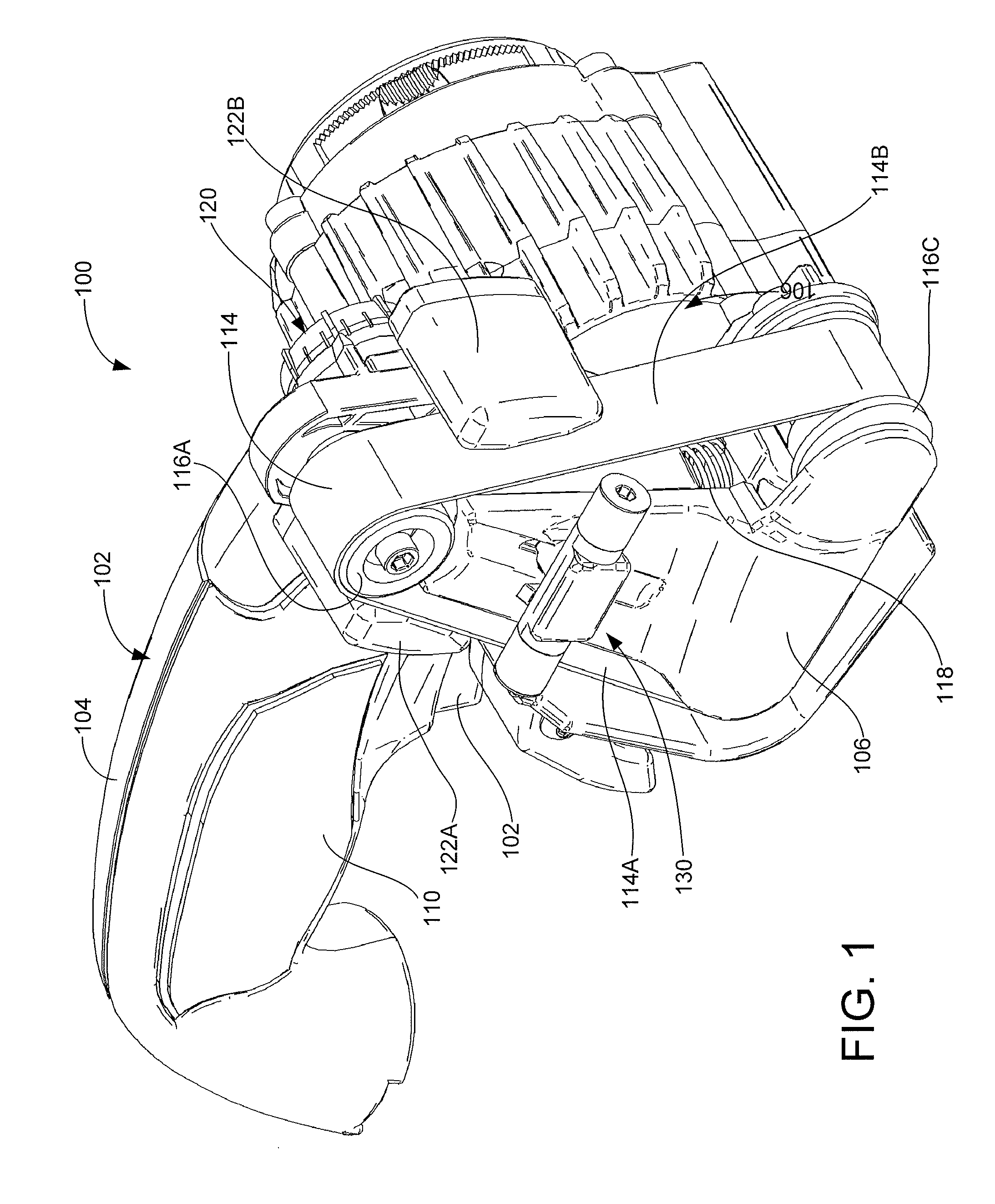
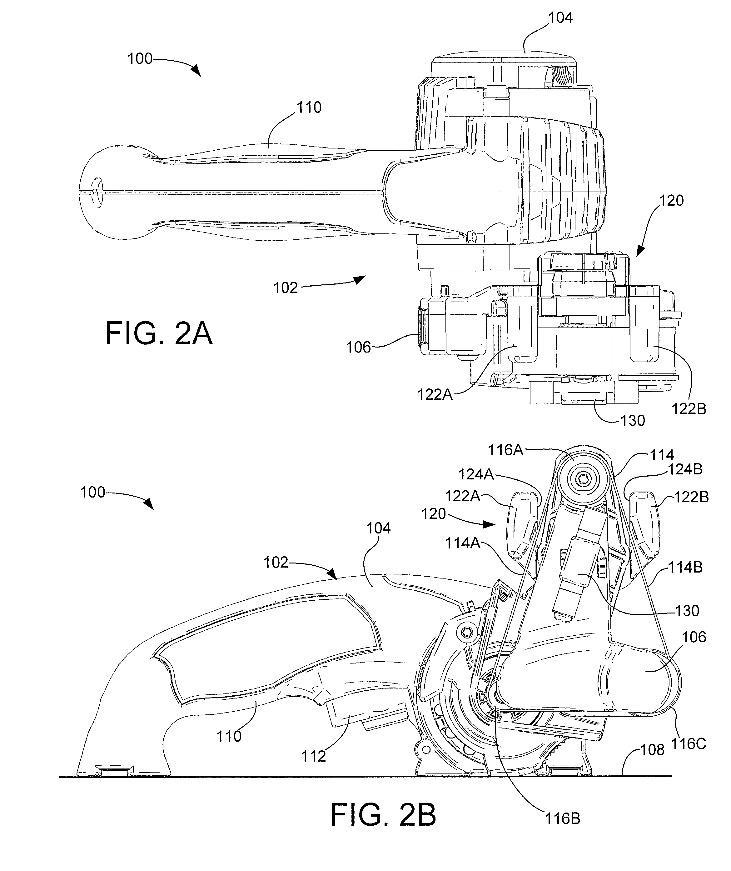
[0028]FIG. 1 shows an exemplary tool sharpener 100 constructed in accordance with some embodiments of the present disclosure. The tool sharpener 100 is configured to sharpen a variety of tools with different configurations of cutting edges. Top and front side views of the tool sharpener 100 are provided in FIGS. 2A and 2B. The tool sharpener 100 is characterized as a hand-held powered sharpener.

[0029]The tool sharpener 100 includes a base structure 102 which encloses and / or supports various components of interest. The structure 102 includes a main body 104 and a sharpening attachment assembly 106. The sharpening attachment assembly 106 can be removably mated with the main body 104 to facilitate various sharpening operations described below. As desired, other operable attachments (not separately shown) can be installed on the main body 104 to carry out other motor-driven functions.

[0030]The main body 104 is adapted to be securely placed on a base surface 108 (FIG. 2B) or, alternative...


PUM

PropertyMeasurementUnit
Forceaaaaaaaaaa
Angleaaaaaaaaaa
Abrasiveaaaaaaaaaa

Abstract

Apparatus for sharpening a cutting tool. In some embodiments, a tool sharpener includes an abrasive medium having an abrasive surface. A stationary tool support guide provides a guide surface that supports a side of the tool during presentation of a cutting edge of the tool against the abrasive surface. A rotatable edge guide has a roller member with a curvilinearly extending outer surface. The roller member is rotatable about an edge guide roller axis and is moveable between a deployed position and a retracted position. In the deployed position, the roller member is positioned to engage, via rolling contact, the cutting edge during the presentation of the cutting edge against the abrasive surface. In the retracted position, the roller member is positioned to provide a non-contacting clearing relation with the cutting edge during said presentation.

Description

BACKGROUND[0001]Cutting tools are used in a variety of applications to cut or otherwise remove material from a workpiece. A variety of cutting tools are well known in the art, including but not limited to knives, scissors, shears, blades, chisels, spades, machetes, saws, drill bits, etc.[0002]A cutting tool often has one or more laterally extending, straight or curvilinear cutting edges along which pressure is applied to make a cut. The cutting edge is often defined along the intersection of opposing surfaces that intersect along a line that lies along the cutting edge.[0003]Cutting tools can become dull over time after extended use. It can thus be desirable to subject a dulled cutting tool to a sharpening operation to restore the cutting edge to a greater level of sharpness. A variety of sharpening techniques are known in the art, including the use of grinding wheels, whet stones, abrasive cloths, etc. While these and other sharpening techniques have been found operable, there is a...

Claims


Application Information

Patent Timeline
IPC IPC(8): B24B3/36B24B23/06B24B23/00B24B23/02
CPCB24B3/36B24B23/005B24B23/06B24B23/02B24B21/00B24B41/066B24B3/24B24B3/52B24B3/54
Inventor DOVEL, DANIEL T.
Owner DAREX
Why Eureka
Try Eureka