

Seat belt device for the vehicle seat
- Summary
- Abstract
- Description
- Claims
- Application Information
AI Technical Summary
Benefits of technology
Problems solved by technology
Method used
Image

Examples
embodiment 1
[0045]The embodiments of this invention will be described in detail, with reference to the accompanying drawings.
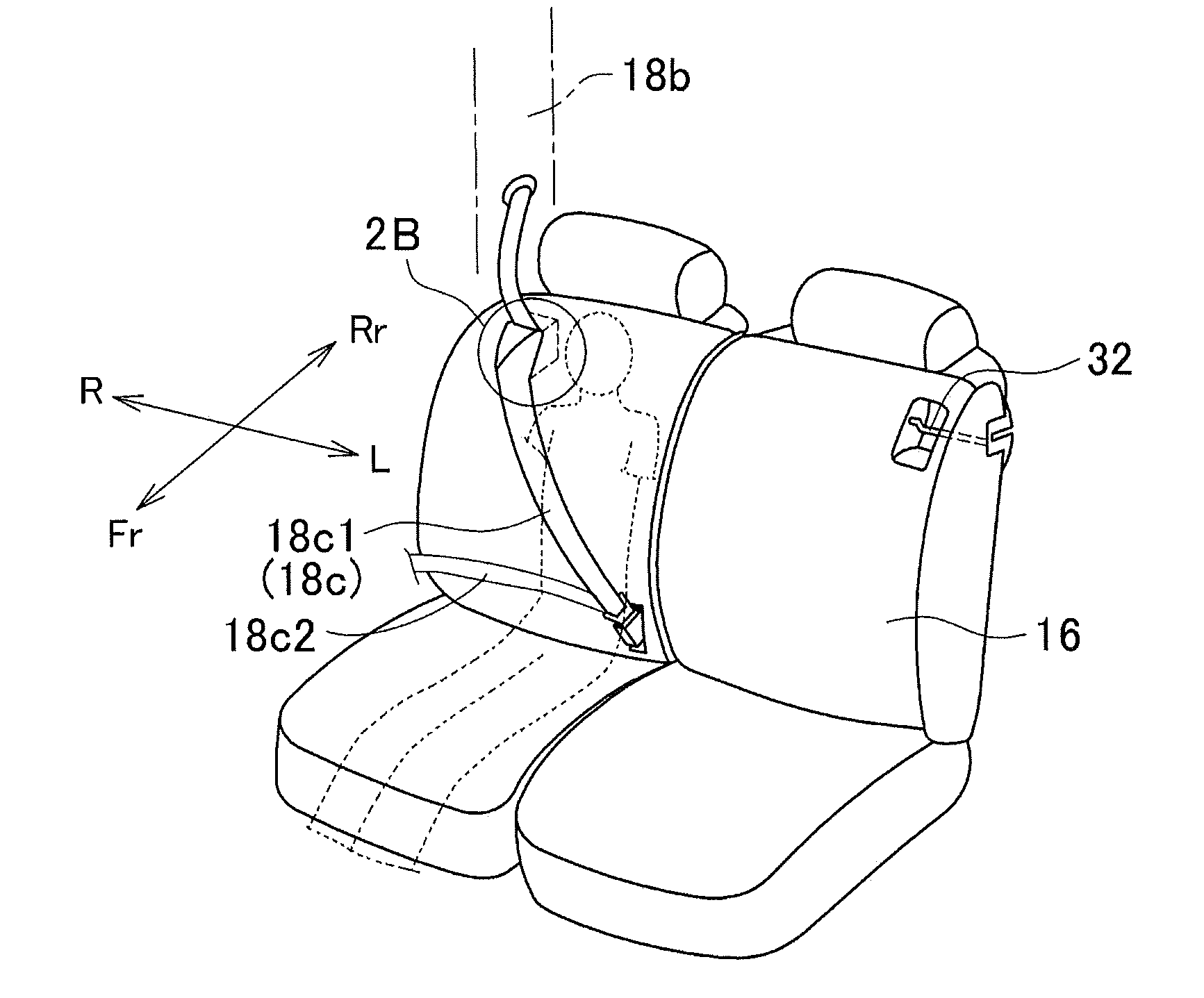
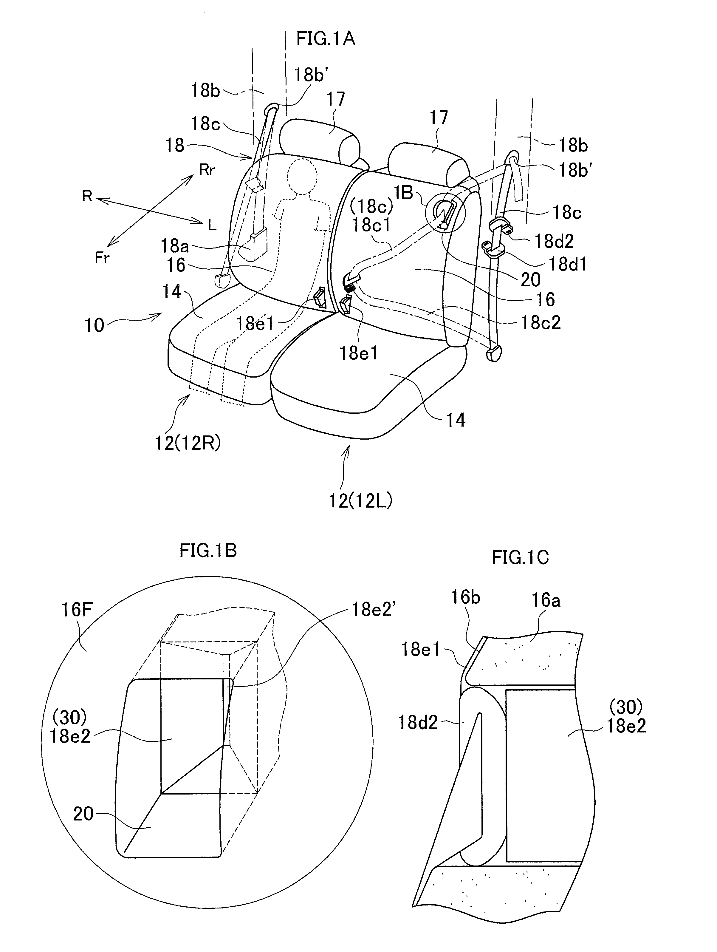
[0046]As shown in FIG. 1A, the vehicle seat 10 has two rear seats 12 (seats 12L and 12R) arranged side by side. Each of the left and right seats 12 (seats 12L and 12R) comprises a seat cushion 14 and a seatback 16. The seatback 16 is coupled to the seat cushion 14 and can be folded forward to the seat cushion. A headrest 17 is mounted on the top of the seatback 16.
[0047]In the drawings, arrows Fr and Rr indicate the forward and backward directions of the vehicle seat 10, and L and R indicate the leftward and rightward directions of the vehicle seat 10.
[0048]The seat cushion 14 and the seatback 16 have basic structures well known in the art. The seatback 16, for example, comprises a seatback frame and a seat pad 16a. The seatback frame is composed of left and right side frames and a connecting pipe connecting the upper ends of the left and right side frames, and is therefo...
embodiment 2
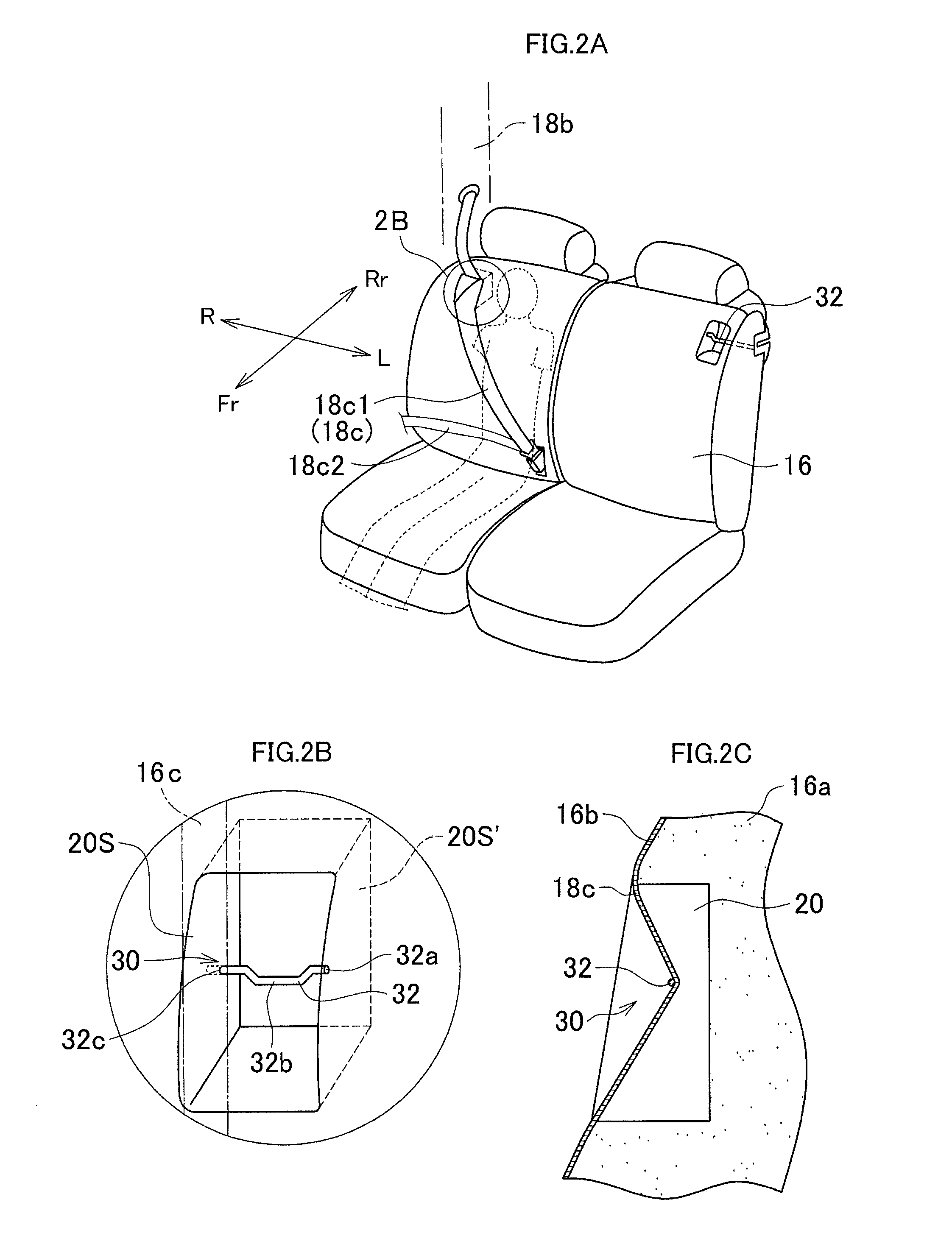
[0066]Embodiment 2 shown in FIGS. 2A to 2C will be described. The components identical to those of the embodiment described above (Embodiment 1) are designated by the same reference numbers, and will not be described. The components distinguishing Embodiment 2 form Embodiment 1 will be described in the main.
[0067]Embodiment 2 differs from Embodiment 1 in that a striker is embedded in the hole 20, not the buckle 18e2 as in Embodiment 1.
[0068]In Embodiment 2, the striker 32 is shaped like a cantilever, and its inner end (close to the vertical centerline of the seat) is the free end. The striker 32 shaped like a cantilever extends in the hole in the left-right direction from, for example, the outer side 20S (pillar-side) of the hole. The distal end (inner end) of the striker is a free end, and spaced from the inner side 20S′ of the hole. A part of the striker, for example the middle part 32b, is bent twice, forming a stepped part. In FIGS. 2B and 2C, the hole 20 is shown as a bottomed ...
embodiment 3
[0089]FIGS. 6A to 6C show Embodiment 3 of this invention. The components identical to those of the embodiments described above (Embodiments 1 and 2) are designated by the same reference numbers, and will not be described. The components distinguishing Embodiment 3 from Embodiments 1 and 2 will be described in the main.
[0090]In Embodiments 1 and 2, a hole is made by cutting an upper-front part of the seatback. In Embodiment 3, a hole is made by cutting through an upper-front part of the seatback. Further, in Embodiment 1 the engaging means is the second buckle located in the hole (bottomed hole or through hole), and in Embodiment 2 the striker located in the hole (through hole or bottomed hole). In Embodiment 3, the engaging means is the striker arranged at the back of the hole (through hole). Embodiment 3 differs in these respects from Embodiments 1 and 2.
[0091]In Embodiment 3, a hole (through hole) 120 is cut through the upper-front part 16F of the seatback and may be positioned at...
PUM
 Abstract
Description
Claims
Application Information