Method and apparatus for releasably immobilizing an attachment to an external object

Inactive Publication Date: 2015-12-03
JUNGEBERG KENNETH ALVIN
View PDF0 Cites 2 Cited by
  • Summary
  • Abstract
  • Description
  • Claims
  • Application Information

AI Technical Summary

Benefits of technology

The patent text describes a two-piece housing that is compressed around a spherical core using a strap clamp with a tightening mechanism. This allows for better hoop compression of the sphere to immobilize an object, like a shaft. The technical effect is improved immobilization of objects using a more secure and effective method.

Problems solved by technology

The complexity and size of an assembly of mechanisms to do this, along with the inefficiency of having to orient and then lock three mechanisms to achieve a particular position or orientation is cumbersome at best and can be frustrating for the operator as the operator attempts to align a connection in a three dimensional space.
This again makes such a system difficult to use causing frustration by the user and unreliable clamping with variable clamping forces needed depending on how the core is aligned with the clamp.

Method used


Image

  • Method and apparatus for releasably immobilizing an attachment to an external object
  • Method and apparatus for releasably immobilizing an attachment to an external object
  • Method and apparatus for releasably immobilizing an attachment to an external object

Examples


Embodiment Construction

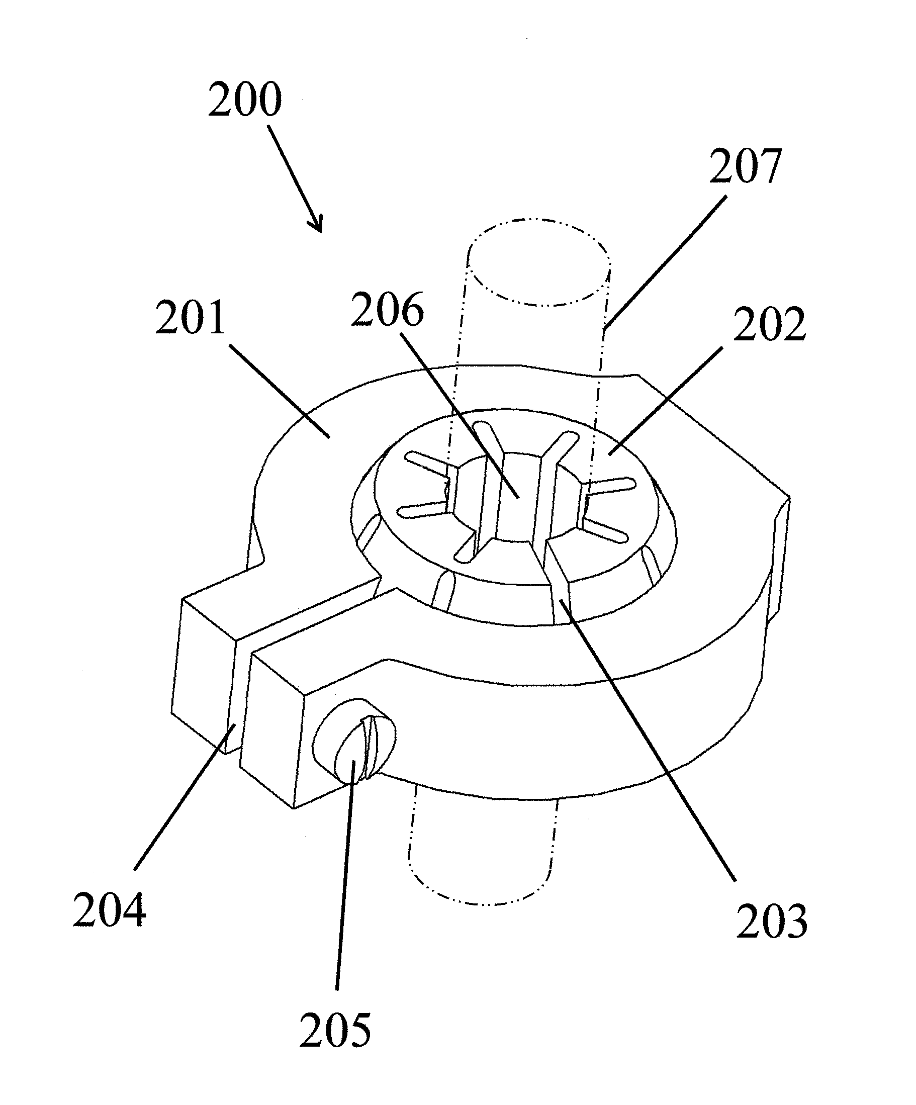
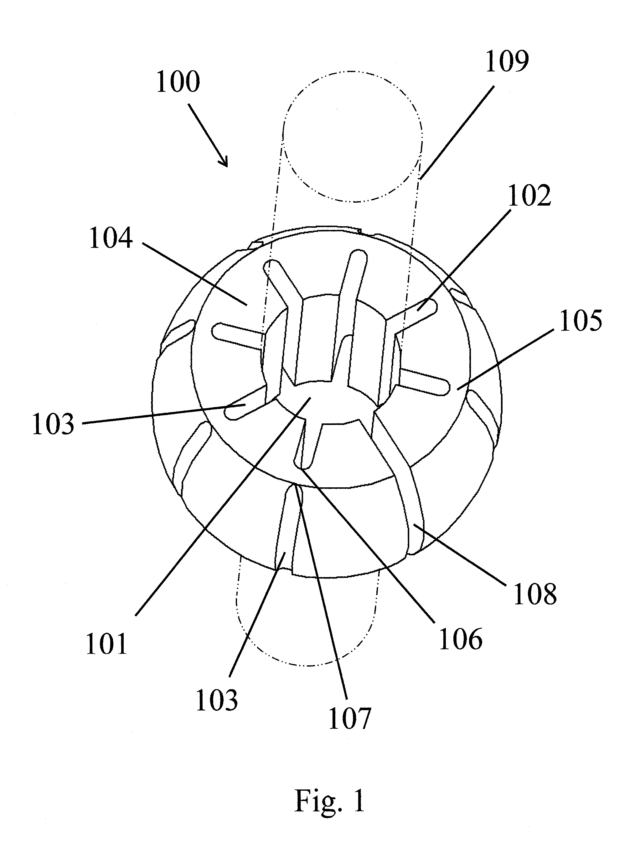
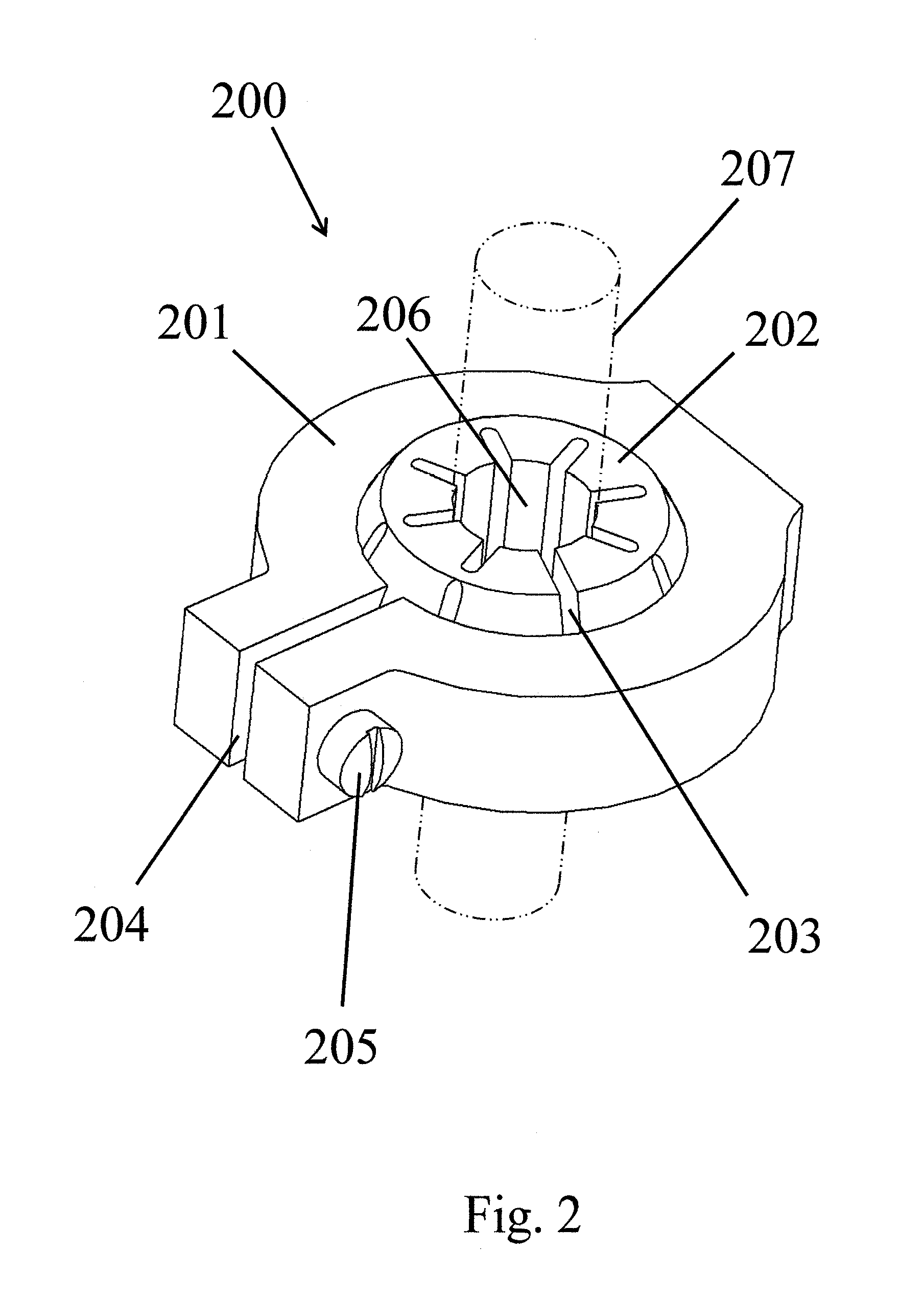
[0031]A spherical bearing, sometimes called a spherical joint, is provided that permits not only ease of alignment but also easily maintained alignment when releasably immobilizing an attachment to a shaft. The joint comprises a spherical inner core which is surrounded by a housing around the core. The joint apparatus does not require careful alignment of the housing and core to efficiently perform its function. To overcome the problem of maintaining alignment and / or immobilization of the item attached to the bearing, the spherical inner core is modified with a series of structural modifications called relief cuts to assure maximum immobility when the bearing or joint is clamped on the shaft regardless of the orientation of the core relative to the clamp housing.

[0032]FIG. 1 shows an embodiment of such a spherical core 100 providing an annular hole 101 through the center of the core 100 for securing to an example external object, in this case a mounting shaft 109 that is round in sh...


PUM

PropertyMeasurementUnit
Pressureaaaaaaaaaa
Diameteraaaaaaaaaa
Flexibilityaaaaaaaaaa

Abstract

A spherical bearing for releasably immobilizing an attachment to a shaft or other external object is provided. The spherical bearing comprises a truncated flexible spherical core with an annular hole through the center of the spherical core for appending the core on the shaft or external object. Segments around the spherical core are created by relief cuts in the spherical core, and deflection flexure points displaced from the annular hole are formed by the relief cuts in the core. A housing provides compression against the core and immobilization of the shaft or other external object.

Description

CROSS REFERENCE TO RELATED APPLICATIONS[0001]This application is a divisional and continuation-in-part application of co-pending U.S. patent application Ser. No. 13 / 625,915, filed Sep. 25, 2012, which claims the benefit of U.S. Provisional Patent Application No. 61 / 539,032, filed Sep. 26, 2011. This application is also a continuation-in-part of co-pending U.S. patent application Ser. No. 13 / 669,236, filed Nov. 5, 2012, which takes priority from U.S. Provisional Patent Application No. 61 / 555,295, filed Nov. 3, 2011. The contents of all of application Ser. Nos. 13 / 625,915, 61 / 539,032, 13 / 669,236, and 61 / 555,295 are incorporated herein by reference.BACKGROUND[0002]When working with a mechanical apparatus, it is often desirable to connect an element of the apparatus or the entire apparatus to an external object such as a shaft. The connected object or shaft can arise from nearly any source and range from a free standing or floating shaft to a securely positioned shaft or other object sp...

Claims


Application Information

Patent Timeline
IPC IPC(8): F16C11/06F16C43/02
CPCF16C11/0695Y10T29/49666F16C43/02F16C11/0604F16C11/0614F16C11/0685F16C11/106Y10T29/49647
Inventor JUNGEBERG, KENNETH ALVIN
Owner JUNGEBERG KENNETH ALVIN
Why Eureka
Try Eureka