
Method and device for inspecting and tailoring a moving product web

a technology for moving products and webs, applied in the field of methods for inspecting and tailoring moving product webs, can solve the problems of generating additional waste, space-consuming and costly, and requiring separation of various areas of product webs, and achieves the effect of substantially more flexibility in handling and easy integration into existing production lines

Inactive Publication Date: 2015-12-03
ADVANCED VISION TECH
View PDF9 Cites 10 Cited by
  • Summary
  • Abstract
  • Description
  • Claims
  • Application Information

AI Technical Summary

Benefits of technology

This patent describes a method for inspecting a moving product web using a camera or other imaging method to capture sections of the web. These captured sections are compared with reference values to detect any defects. The comparison is made using various tolerances, such as displacement or rotation. The inspection can be done without adding any additional markers or code to the product web, which means it can be used without producing any extra waste. By measuring the length of the product web at different points in the process, information can be obtained to identify specific sections that may be defective. This information can then be used to take appropriate action, such as separating out the defective sections or repairing them. The method is flexible and can be easily integrated into existing production lines without needing to add any additional equipment.

Problems solved by technology

However, part of the product web is therefore needed for the markings, which thus generates additional waste.
In addition, an additional application or printing unit may have to be set up for the markings, which is space-consuming and costly.
However, an unambiguous assignment of the defective points determined in the inspection method to the respective section of the moving product web must be provided.
However, because of defective printed images, defective points of the product web or other sources of defects, various areas of the product web—in particular faulty products—have to be separated out again and again.
For this task, however, the relative running length determination is inadequate.
It would no longer be possible to reconstruct the position of the defects.
However, this measure in turn leads to additional wastage, since the code takes up part of the product web.
Finally, it is quite unlikely that, in the case of a defective print, the running length code applied contemporaneously is correct and legible.

Method used


Image

  • Method and device for inspecting and tailoring a moving product web
  • Method and device for inspecting and tailoring a moving product web
  • Method and device for inspecting and tailoring a moving product web

Examples


Embodiment Construction

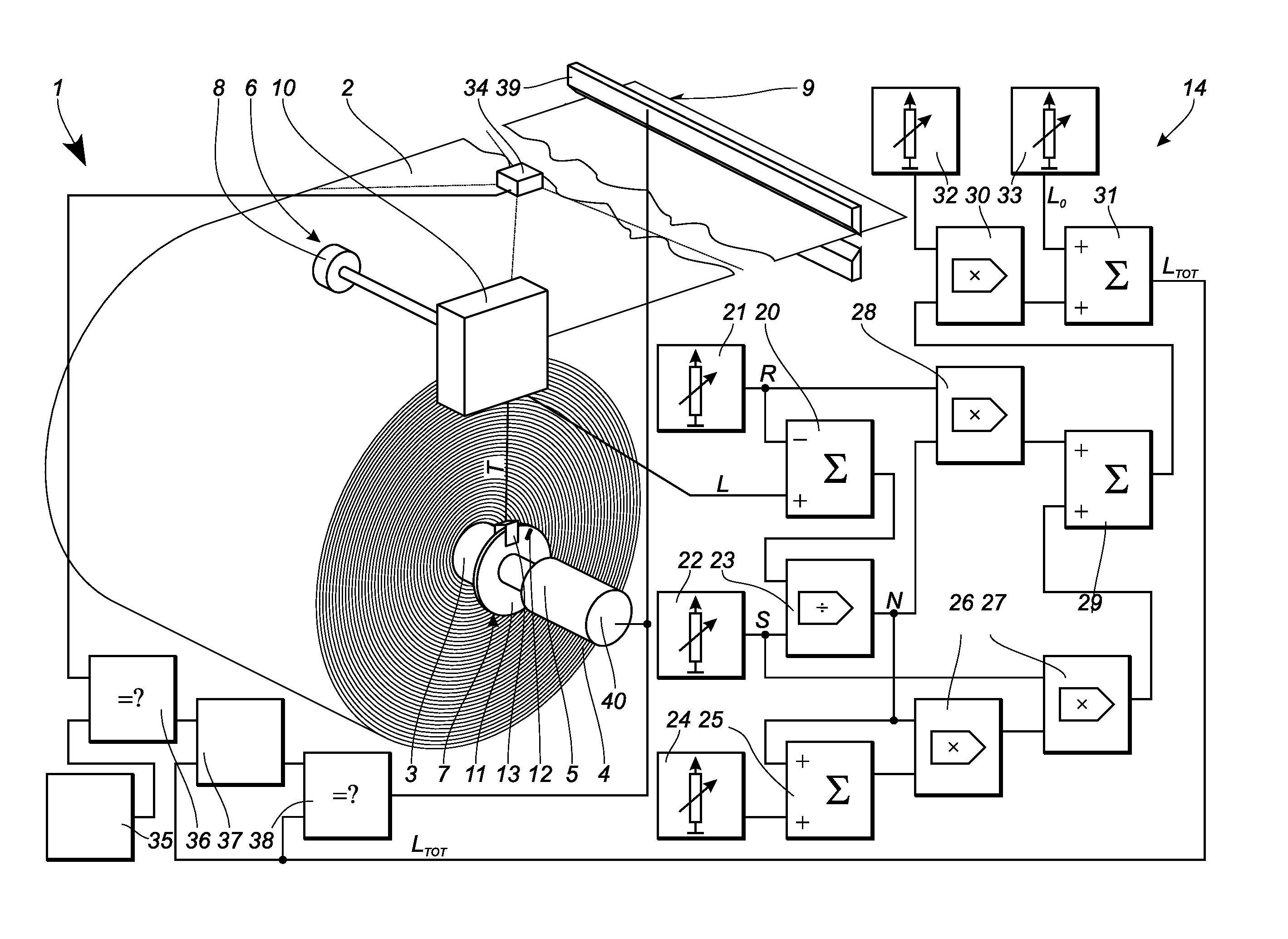
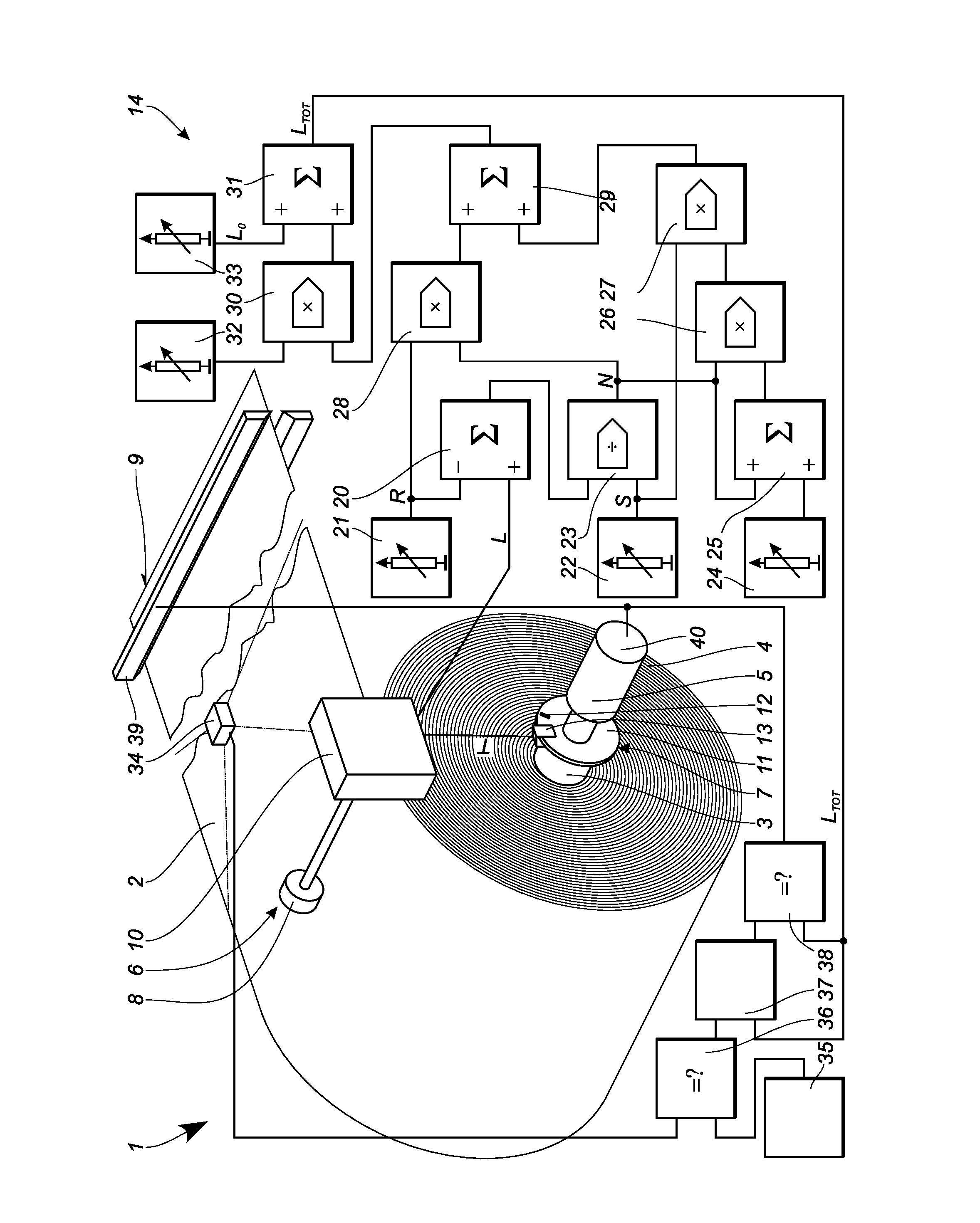
[0026]A device 1 is used both to inspect and to tailor a moving product web 2. In this case, the product web 2 is partly wound up onto a winder 3 and, on the latter, is arranged in various layers 4 over one another. The winder 3 is arranged such that it can be rotated about a shaft 5 and is thus driven in rotation by a drive. The shaft 5 can also be operatively connected to a drive 40 or a braking device, not illustrated, and can be designed to transmit torque. However, this is not imperative.

[0027]The winder 3 is operatively connected to a first transmitter 6 and a second transmitter 7. The first transmitter 6 has at least one running wheel 8, which is operatively connected to the product web 2 by a frictional connection. This running wheel 8 captures a relative running length L of the product web 2. This means that, although running path differences can be determined unambiguously and precisely by means of the running wheel 8, the absolute running length LTOT beginning from a star...


PUM


Abstract

In a method for inspecting and tailoring a predefined point of a moving product web (2), the moving product web (2) is located at least partly on a winder (3). Both a relative running length L of the product web (2) and an associated angle of rotation α of the winder (3) are captured. From these values, the absolute running length LTOT of the moving product web (2) is then calculated. A camera (34) captures the moving product web (2). The camera value is compared with a reference value (36) and, together with the absolute running length LTOT of the moving product web (2), is stored in a file (37). At a later time, with the aid of the file (37), the defective points of the moving product web (2) are moved to. The absolute running length LTOT is determined again and compared with the file (37). Therefore, the defective points can easily be separated out from the moving product web (2).

Description

[0001]The present application claims priority to German Patent Application no:DE 10 2014 005 347.4, filed Apr. 11, 2014FIELD OF THE INVENTION[0002]The invention relates to a method for inspecting and tailoring a moving product web, the product web being located at least partly on a winder.DESCRIPTION OF THE PRIOR ART[0003]During the inspection of a moving product web, defective points of the moving product web must be detected and stored in suitable form in order that it is possible to move to said points during the subsequent tailoring operation and to separate them out of the product web. In known inspection methods, this is done by marking the moving product web with appropriate markings, so that the absolute position of the defective points can be determined unambiguously. In the following tailoring operation, these markings must then be assessed. However, part of the product web is therefore needed for the markings, which thus generates additional waste. In addition, an additio...

Claims


Application Information

Patent Timeline
IPC IPC(8): G01N21/84B65H20/00
CPCG01N21/8422G01N2201/12B65H20/00B65H26/02D21G9/0009G01N21/89B65H2553/42B65H2557/62B65H2801/84
Inventor EDER, ALFREDTHOMALLA, ALEXANDERPITTINO, STEPHAN
Owner ADVANCED VISION TECH
Learn More