Device and method for subgingival measurement

a subgingival and measurement device technology, applied in the field of dental measurements, can solve the problems of inaccuracy of the technique, inability to image, measure and model visible parts of the patient's mouth, and inability to provide imaging of subgingival areas

Active Publication Date: 2015-12-03
DENTLYTEC G P L
View PDF4 Cites 62 Cited by
  • Summary
  • Abstract
  • Description
  • Claims
  • Application Information

AI Technical Summary

Problems solved by technology

Such techniques suffer from inaccuracy due to multiple manual steps which can be technically demanding on the dentist as well as invasive and uncomfortable for the patient, especially if subgingival measurement is necessary.
However, such techniques are only able to image, measure and model visible parts of the patient's mouth and generally do not provide imaging of subgingival areas.
CT scanning can provide measurement of subgingival areas, however it does not provide soft tissue measurement.
This separation usually causes bleeding which needs to be stemmed or prevented before measurements can be made.
The process of separation sometimes causes trauma to the gingiva, which can lead to inflammation and permanent damage to the gingiva.
Cord packing is generally a time consuming procedure, stressful and technically demanding for the dental practitioner and painful for the patient.
Dental practitioners may have a dilemma, either to use damaging, painful, technically challenging methods to expose subgingival tooth areas (e.g., cord packing) for measurement or to forgo subgingival measurements resulting in either ill-fitting prosthetics or prosthetics with unpleasing aesthetics where the border between the prosthetic and original tooth structure is visible above the gum line.

Method used


Image

  • Device and method for subgingival measurement
  • Device and method for subgingival measurement
  • Device and method for subgingival measurement

Examples


Embodiment Construction

[0103]The present invention, in some embodiments thereof, relates to dental measurements, and more particularly, but not exclusively, to a device and method for subgingival measurement.

Overview

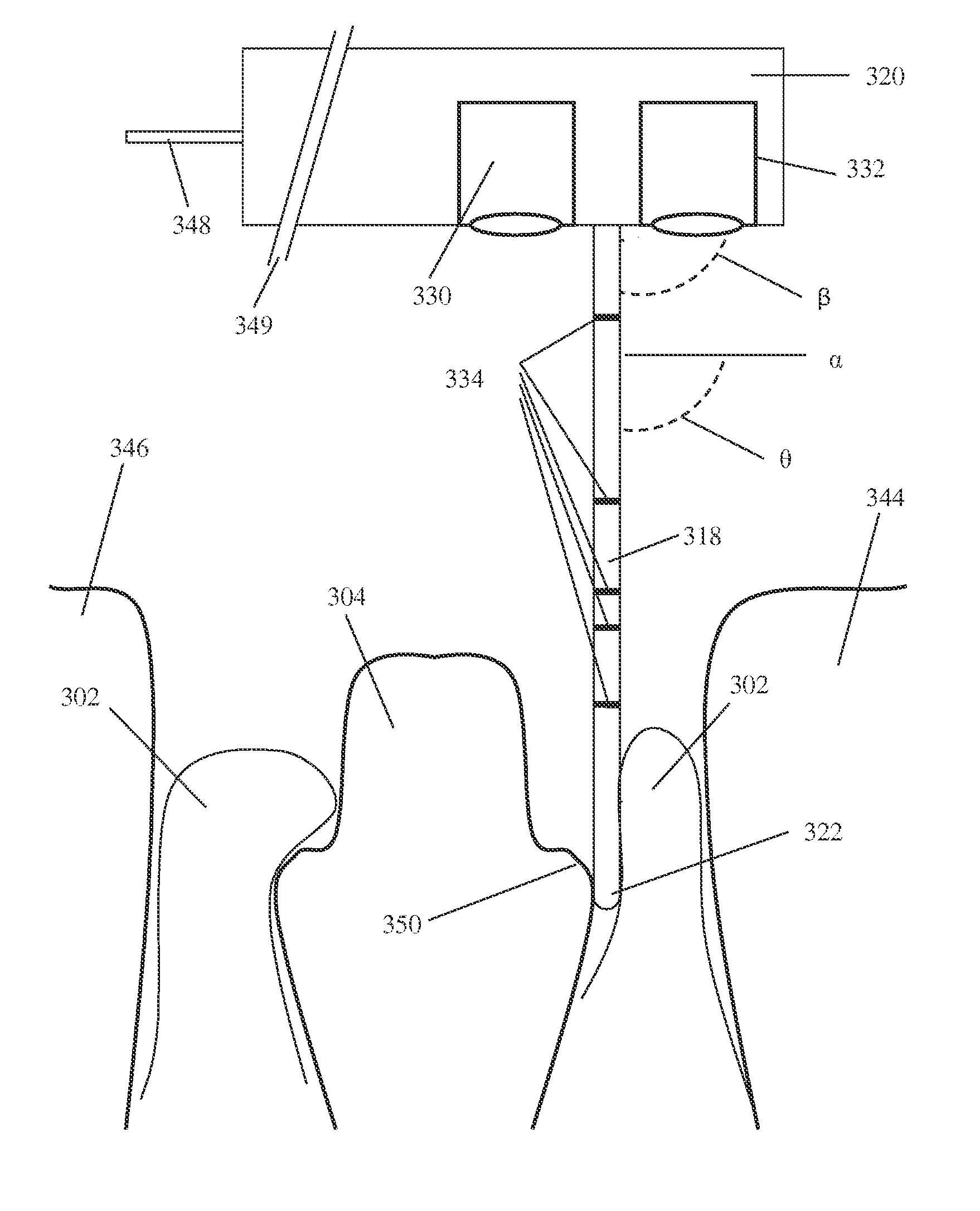
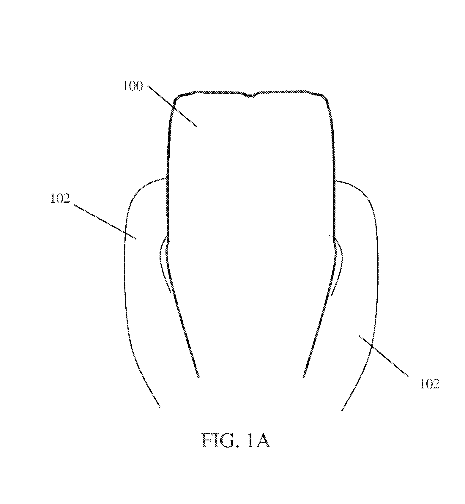
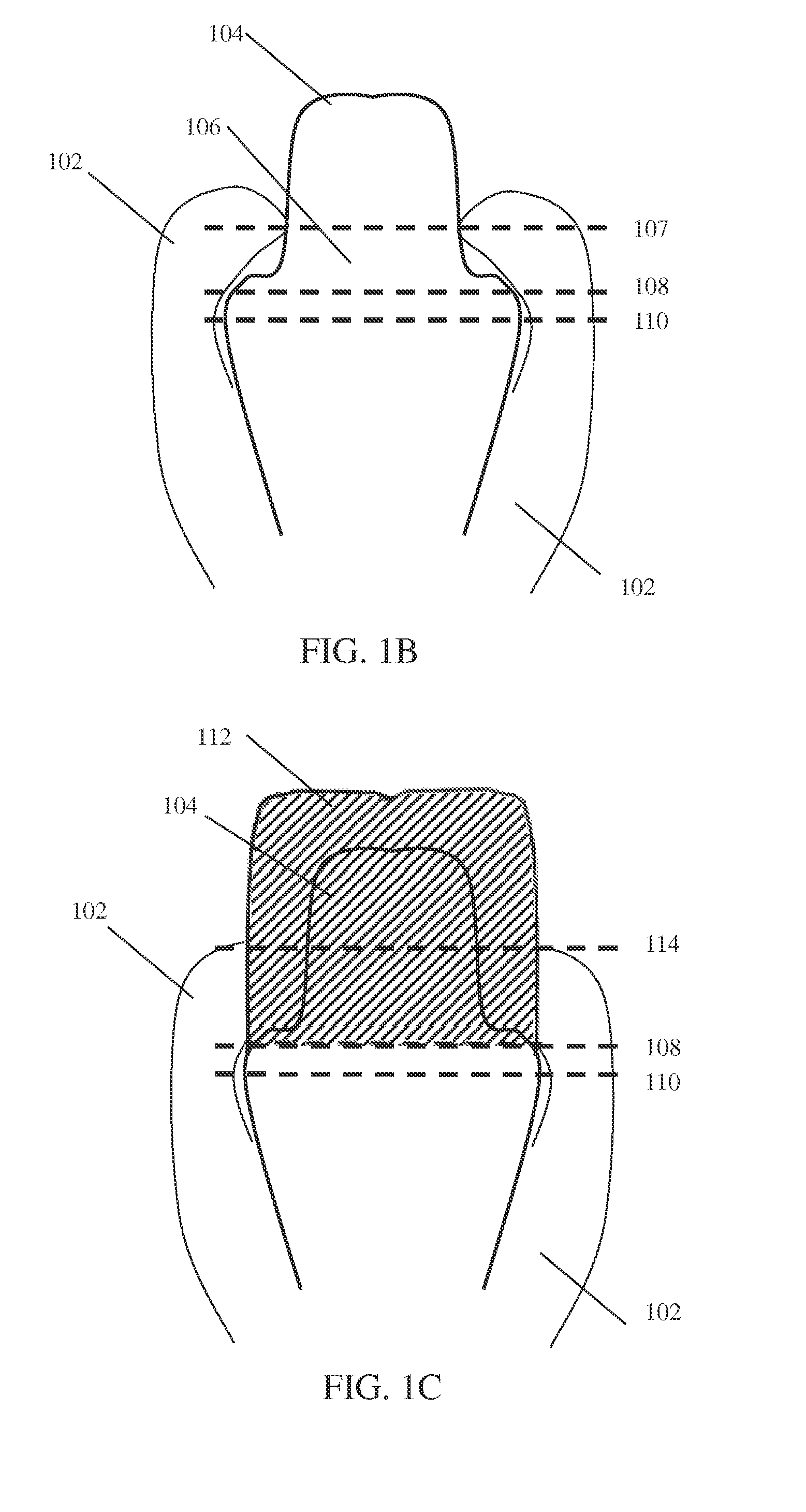
[0104]An aspect of some embodiments of the invention relates to measuring regions of a tooth, especially subgingival portions, for example, using contact measurement. In some embodiments a stylus tip is put into contact with a subgingival surface of a tooth. The subgingival surface of the tooth is then measured by estimating a location of the stylus tip with respect to a visible reference of a visible portion of the tooth (e.g., tooth portion surface topography, marker on the tooth, stylus) giving a stylus tip location. In some embodiments measurement is using images / s collected by an imager. In some embodiments the stylus is attached to the imager. In some embodiments the imager and the stylus are separate components.

[0105]The term ‘stylus’, as used in this document, refers to any elongated m...


PUM


Abstract

A method for measuring regions of a tooth in a mouth including: measuring at least one surface point on a surface of the tooth with respect to an element mechanically coupled to said surface point; determining a location of at least one visible reference mechanically coupled to said surface point with respect to said element; estimating a location of said surface point with respect to said visible reference. A device used for such measuring may include a main body comprising a final optical element of an imager which defines an optical field of view directed in a first direction; and a measurement element coupled to said main body extending generally in said first direction; where a tip of said measurement element is sized and shaped to be inserted between a tooth and adjacent gingiva; where said optical field of view is sized to image at least part of a tooth.

Description

RELATED APPLICATION / S[0001]This application claims the benefit of priority under 35 USC §119(e) of U.S. Provisional Patent Application No. 61 / 745,744 filed Dec. 24, 2012, the contents of which are incorporated herein by reference in their entirety.FIELD AND BACKGROUND OF THE INVENTION[0002]The present invention, in some embodiments thereof, relates to dental measurements, and more particularly, but not exclusively, to a device and method for subgingival measurement.[0003]Dental treatments often involve measurement of the patient's mouth. In particular, construction of crowns, bridges and other dental prosthetics generally involves measurement or acquisition of three dimensional model / s of existing dental structures. Often prosthetics extend below the gum line, and measurement of dental structures below the gum line is carried out. Accurate measurement / s and / or modeling can facilitate a good fit of the prosthetic constructed using the measurements / s and / or model / s to the patient's mo...

Claims


Application Information

Patent Timeline
Patent Type & Authority Applications(United States)
IPC IPC(8): G06T17/30A61C19/04G06T15/08A61C9/00H04N5/225G06T7/00
CPCG06T17/30H04N5/225G06T7/0014G06T7/0024G06T7/004G06T2215/16A61C9/0053A61C19/043H04N2005/2255G06T2207/10028G06T2207/30036G06T15/08A61C9/0066A61C13/0004A61C19/04G06T7/30G06T7/70A61C9/0033H04N23/00H04N23/555A61B1/247A61C9/006
Inventor PESACH, BENNYGRAD, YGAELLEHR, BLANC ZACHMELAMED, GEORGY
Owner DENTLYTEC G P L
Why Eureka
Try Eureka