Sound processing system and sound processing method
Active Publication Date: 2015-12-03
PANASONIC INTELLECTUAL PROPERTY MANAGEMENT CO LTD
View PDF25 Cites 37 Cited by
Summary
Abstract
Description
Claims
Application Information
AI Technical Summary
This helps you quickly interpret patents by identifying the three key elements:
Problems solved by technology
Method used
Benefits of technology
Benefits of technology
The invention allows for emphasizing and outputting audio data in a way that directs it towards specific locations on a display screen where capturing video data is shown.
Problems solved by technology
In addition, since an information amount which can be obtained in monitoring only using a video is restricted, a monitoring system has recently appeared in which a microphone is also disposed in addition to the monitoring camera, and thus video data and audio data regarding the vicinity of a monitoring target are obtained.
Method used
Image
Click on the blue label to locate the original text in one second.
Reading with bidirectional positioning of images and text.
Examples
first embodiment
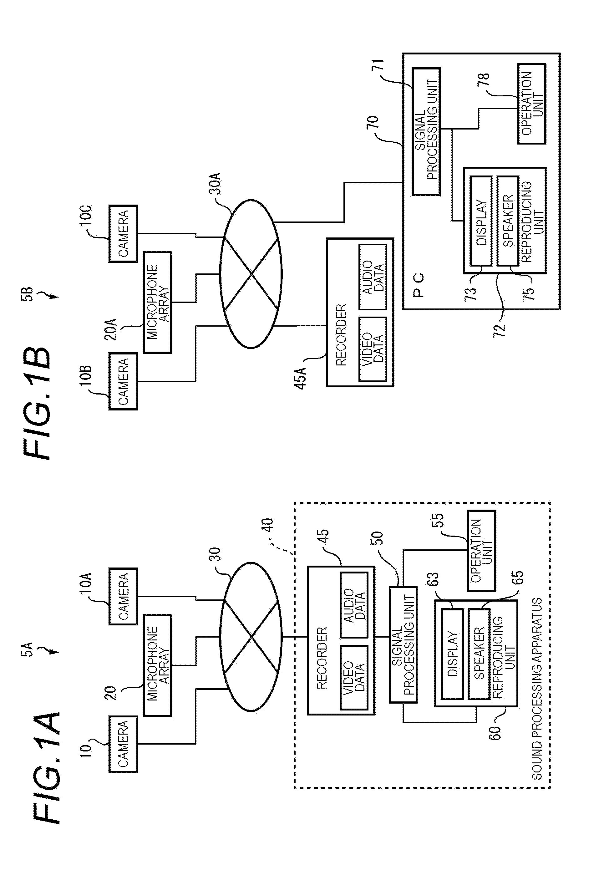
[0054]FIGS. 1A and 1B are block diagrams illustrating configurations of sound processing systems 5A and 5B of respective embodiments. The sound processing system 5A includes monitoring cameras 10 and 10A, a microphone array 20, and a sound processing apparatus 40. The cameras 10 and 10A, the microphone array 20, the sound processing apparatus 40 are connected to each other via a network 30.
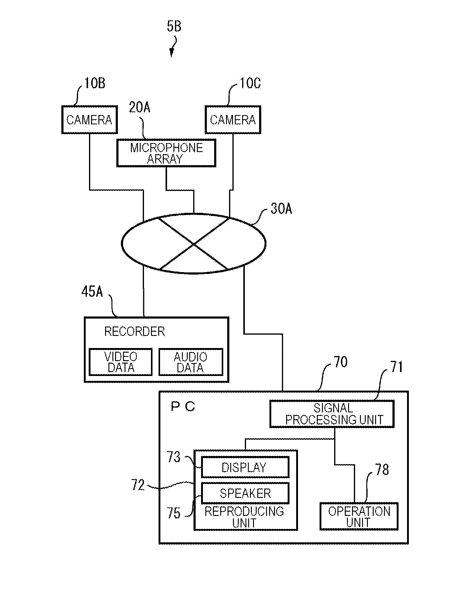
[0055]The sound processing system 5B includes monitoring cameras 10B and 10C, a microphone array 20A, a recorder 45A, and a personal computer (PC) 70. The cameras 10B and 10C, the microphone array 20A, the recorder 45A, and the PC 70 are connected to each other via a network 30A.
[0056]Hereinafter, a description will be made focusing on an operation of each element of the sound processing system 5A, and an operation of each element of the sound processing system 5B will be described in relation to the content which is different from that of the operation of the sound processing system 5A.
[0057]The ...
second embodiment
[0100]In the first embodiment, a description has been made of an example of the usage type of the sound processing system 5A in a case of a single camera. In a second embodiment, a description will be made of an example of a usage type of a sound processing system 5C in a case of a plurality of cameras (for example, two cameras).
[0101]In addition, the sound processing system 5C of the second embodiment has the same configuration as that of the sound processing system 5A or 5B of the first embodiment except for a plurality of cameras (for example, two cameras), and thus description thereof will be omitted by using the same reference numerals for the same constituent elements as those of the sound processing system 5A or 5B of the first embodiment.
[0102]FIG. 7 schematically illustrates an example of a usage type of the sound processing system 5C of the second embodiment. FIG. 7A is a diagram illustrating a state in which two cameras 10 and 10A, a single microphone array 20 located at ...
third embodiment
[0115]In each of the first and second embodiments, a description has been made of an example of the usage type of the sound processing system 5A or 5B in which the camera and the microphone array are provided at different positions on the ceiling. In the third embodiment, a description will be made of an example of a usage type of a sound processing system 5D in which an omnidirectional camera and a microphone array are integrally provided on the same axis.
[0116]In addition, the sound processing system 5D of the third embodiment has the same configuration as that of the sound processing system 5A or the sound processing system 5B of the first embodiment except that an omnidirectional camera and a microphone array are integrally provided on the same axis, and thus description thereof will be omitted by using the same reference numerals for the same constituent elements as those of the sound processing system 5A or 5B of the first embodiment.
[0117]FIG. 9 schematically illustrates an e...
PUM
Abstract
A recorder receives designation of a video which is desired to be reproduced from a user. If designation of one or more designated locations where sound is emphasized on a screen of a display which displays the video is received by the recorder from the user via an operation unit during reproduction or temporary stopping of the video, a signalprocessing unit performs an emphasis process on audio data, that is, the signalprocessing unit emphasizes audio data in directions directed toward positions corresponding to the designated locations from a microphone array by using audio data recorded in the recorder. A reproducing device reproduces the emphasis-processed audio data and video data in synchronization with each other.
Description
TECHNICAL FIELD[0001]The present invention relates to a sound processingsystem and a sound processing method capable of reproducing recorded video data and audio data.BACKGROUND ART[0002]In a monitoring system provided in a factory, a store (for example, a retail store or a bank) or a public place (for example, a library), a plurality of monitoring cameras (for example, pan-tilt cameras or omnidirectional cameras) are connected to each other via a network, and thus high image quality and wide angle of view of video data (including a still image and a moving image; this is also the same for the following description) regarding the vicinity of a monitoring target are realized.[0003]In addition, since an information amount which can be obtained in monitoring only using a video is restricted, a monitoring system has recently appeared in which a microphone is also disposed in addition to the monitoring camera, and thus video data and audio data regarding the vicinity of a monitoring tar...
Claims
Application Information
Patent Timeline
Application Date:The date an application was filed.
Publication Date:The date a patent or application was officially published.
First Publication Date:The earliest publication date of a patent with the same application number.
Issue Date:Publication date of the patent grant document.
PCT Entry Date:The Entry date of PCT National Phase.
Estimated Expiry Date:The statutory expiry date of a patent right according to the Patent Law, and it is the longest term of protection that the patent right can achieve without the termination of the patent right due to other reasons(Term extension factor has been taken into account ).
Invalid Date:Actual expiry date is based on effective date or publication date of legal transaction data of invalid patent.

