Line stabilizer

Active Publication Date: 2015-12-10
NAT OILWELL VARCO LP
View PDF15 Cites 7 Cited by
  • Summary
  • Abstract
  • Description
  • Claims
  • Application Information

AI Technical Summary

Benefits of technology

The patent describes a device that keeps a wire or cable stable without bouncing or swinging too much. The device has a guide that helps keep the wire in a proper place. This design is safer and easier to use than other devices because it has fewer parts, so it's less likely for parts to get dropped or thrown.

Problems solved by technology

However, traditional stabilizers are cumbersome and have many parts often including plates and supported wheels with axles, bearings, and the like.
Some stabilizers are known to have 77 different parts and are prone to losing or dropping the parts while in use.
The objects may easily become projectiles as they are flung in any direction at very high speeds.
Still further, such failures may occur without warning.
This can be dangerous for crews and can damage equipment.

Method used


Image

  • Line stabilizer
  • Line stabilizer
  • Line stabilizer

Examples


Embodiment Construction

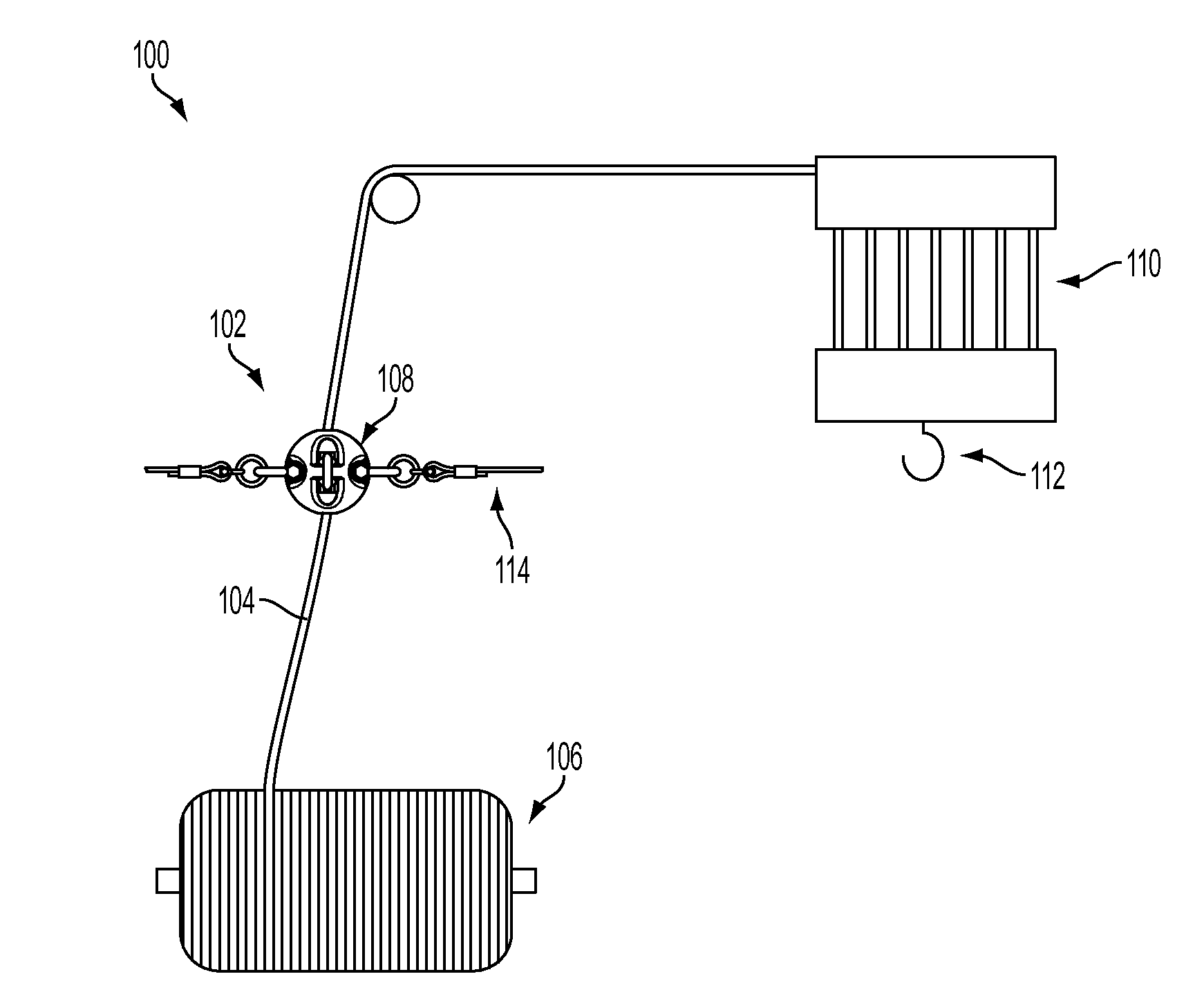
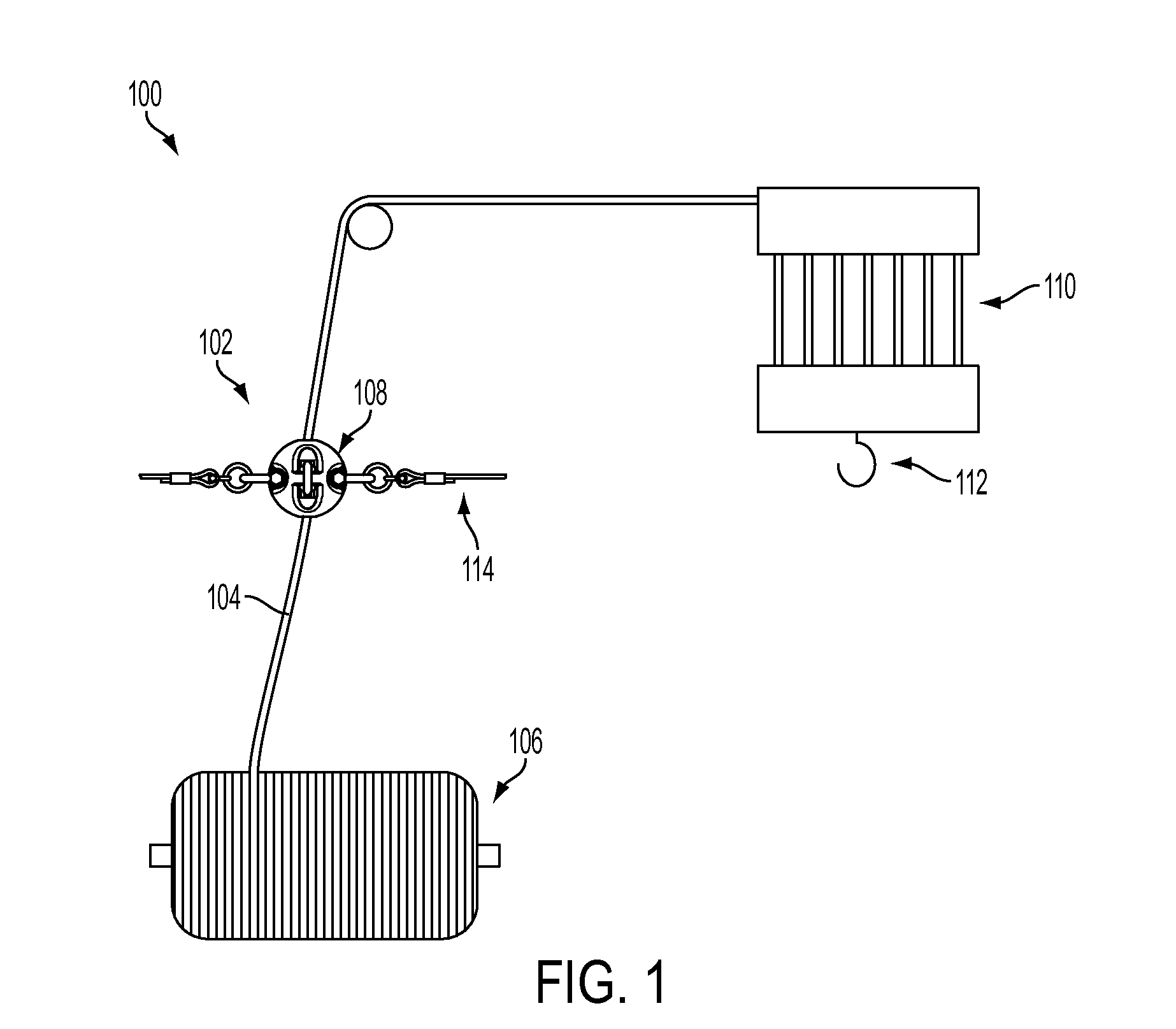
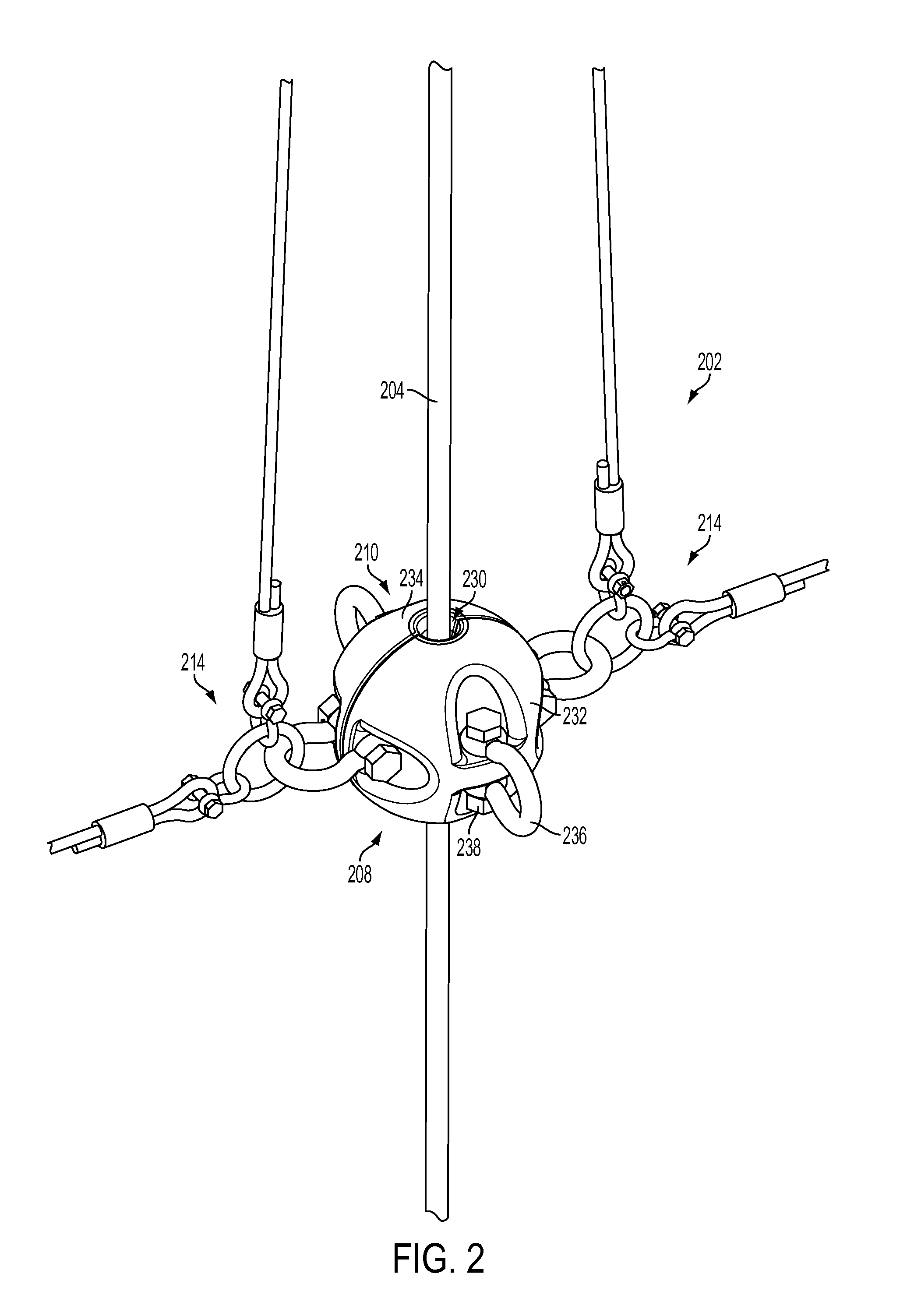
[0040]The present disclosure, in some embodiments, relates to a line stabilizer for positioning along a line and for controlling lateral motions of the line. In particular, in some embodiments, the stabilizer may be for use with a fast line or wire line of an oil derrick where the line coming off of the winch drum may be moving at high speeds and may have a tendency to wave, whip, or otherwise move laterally relative to the direction of motion of the line. The presently described stabilizer may be designed with fewer parts assembled in a manner particularly adapted to reduce and / or prevent the number of dropped objects. For example, in lieu of rollers or other moving parts, in some embodiments, the stabilizer may include dedicated wear parts to safe guard primary functions and parts and the dedicated wear parts may include indicators allowing the user to determine the amount of wear on the part such that informed decisions about repair and / or replacement may be made before parts fal...


PUM

PropertyMeasurementUnit
Diameteraaaaaaaaaa
Wear resistanceaaaaaaaaaa
Electrical resistanceaaaaaaaaaa

Abstract

A stabilizer for a line may include a guide configured for arrangement on the line to resist and / or dampen lateral motions of the line where the guide may include a guide jacket having a static sleeve configured to allow the line to pass through the guide and a fortifying bracket configured to reinforce the guide jacket and configured to interface with a hanging system to support the guide jacket and maintain the guide jacket in position on the line.

Description

FIELD OF THE INVENTION[0001]The present disclosure relates to a stabilizer or guide for managing relative movement with a line such as a wire, guide wire, guideline, cable, cord, rope, wire rope or other relatively flexible tension carrying element. More particularly, the present disclosure relates to a stabilizer for permitting movement of the line through the stabilizer while reducing, damping, controlling, or otherwise inhibiting lateral motion or whipping of the line. Still more particularly, the present disclosure relates to a fast line stabilizer for use on a fast line or wire line of an oil derrick where the lifting line extends from the winch or drum upward toward the crown block of the derrick.BACKGROUND OF THE INVENTION[0002]The background description provided herein is for the purpose of generally presenting the context of the disclosure. Work of the presently named inventors, to the extent it is described in this background section, as well as aspects of the description ...

Claims


Application Information

Patent Timeline
IPC IPC(8): B66D1/36
CPCB66D1/36
Inventor KRIJNEN, ANTON
Owner NAT OILWELL VARCO LP
Why Eureka
Try Eureka