Kind of light emitting diode luminaire

a light-emitting diode and luminaire technology, applied in the field of luminaires, can solve the problems of poor heat dissipation effect, fixed overall structure, and inconvenient angle adjustment, and achieve the effect of convenient angle adjustment, simple structure and improved heat dissipation

Inactive Publication Date: 2015-12-10
SHENZHEN YAORONG TECH
View PDF29 Cites 6 Cited by
  • Summary
  • Abstract
  • Description
  • Claims
  • Application Information

AI Technical Summary

Benefits of technology

[0018]1) The radiator of the Light Emitting Diode luminaire is equipped with through-holes which makes its top and bottom connected, forming air convection and facilitating air exchange. It is also designed with a plurality of heat sinks, with gap between them, allowing for speedup of heat dissipation and better heat dissipation effect;
[0019]2) Light Emitting Diode luminaire is equipped with adapter assembly which comprises the first adapter and the second adapter; they are connected through rotating activity of tooth structures, allowing for adjustment of the angle.
[0020]3) Light Emitting Diode luminaire comprises a lens module board which adopts the waterproof and optical integrated design, with simple and elegant outlook. A very good waterproof effect is achieved without using glass board to separate the lenses and the outside.
[0021]4) The lenses on the lens module board are polarized lenses, producing polarized distribution light for large angle of lighting, achieving scattered lighting, having large lighting range.
[0022]5) The installment of lighting arrester increases the safety and improves the working life of LED luminaire.

Problems solved by technology

The Light Emitting Diode (LED) luminaire in existence is not convenient for air convection, nor for timely discharge of hot-air, and heat dissipation effect is poor.
In addition, the overall structure is fixed and it is not convenient to adjust the angle.
Though the purpose of waterproofing is achieved, the structure is not simple.

Method used


Image

  • Kind of light emitting diode luminaire
  • Kind of light emitting diode luminaire
  • Kind of light emitting diode luminaire

Examples


Embodiment Construction

[0031]In order to better understanding the invention, the invention is further described with combination of the figures and embodiments.

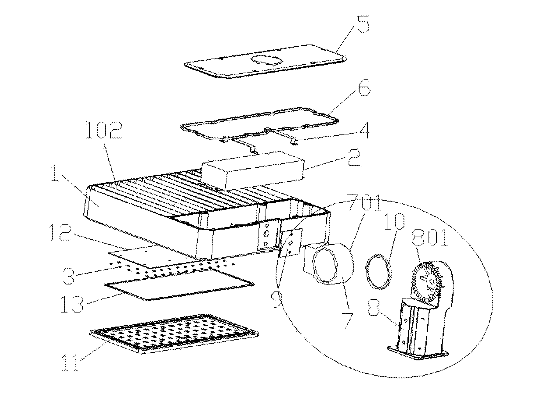
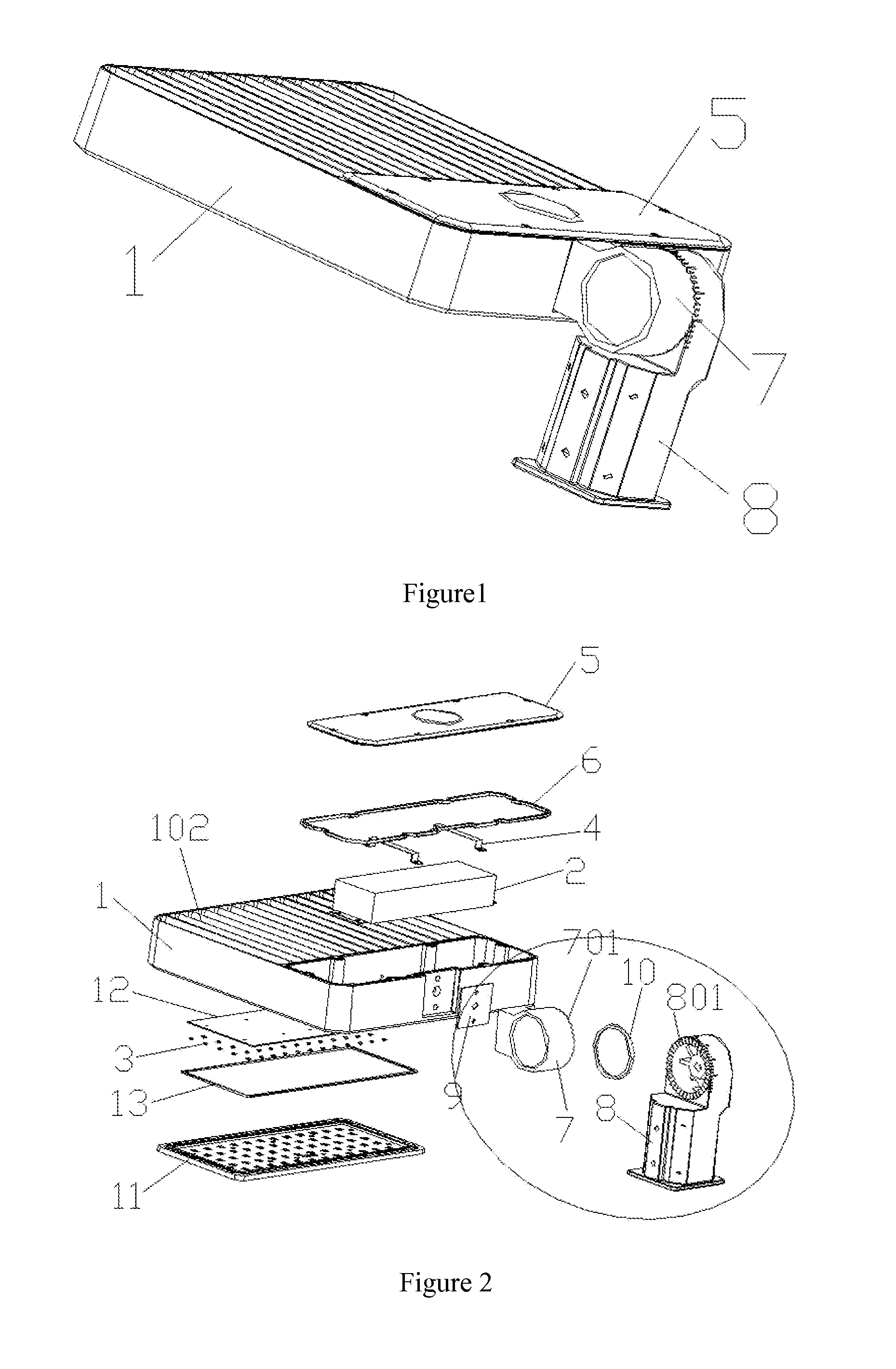
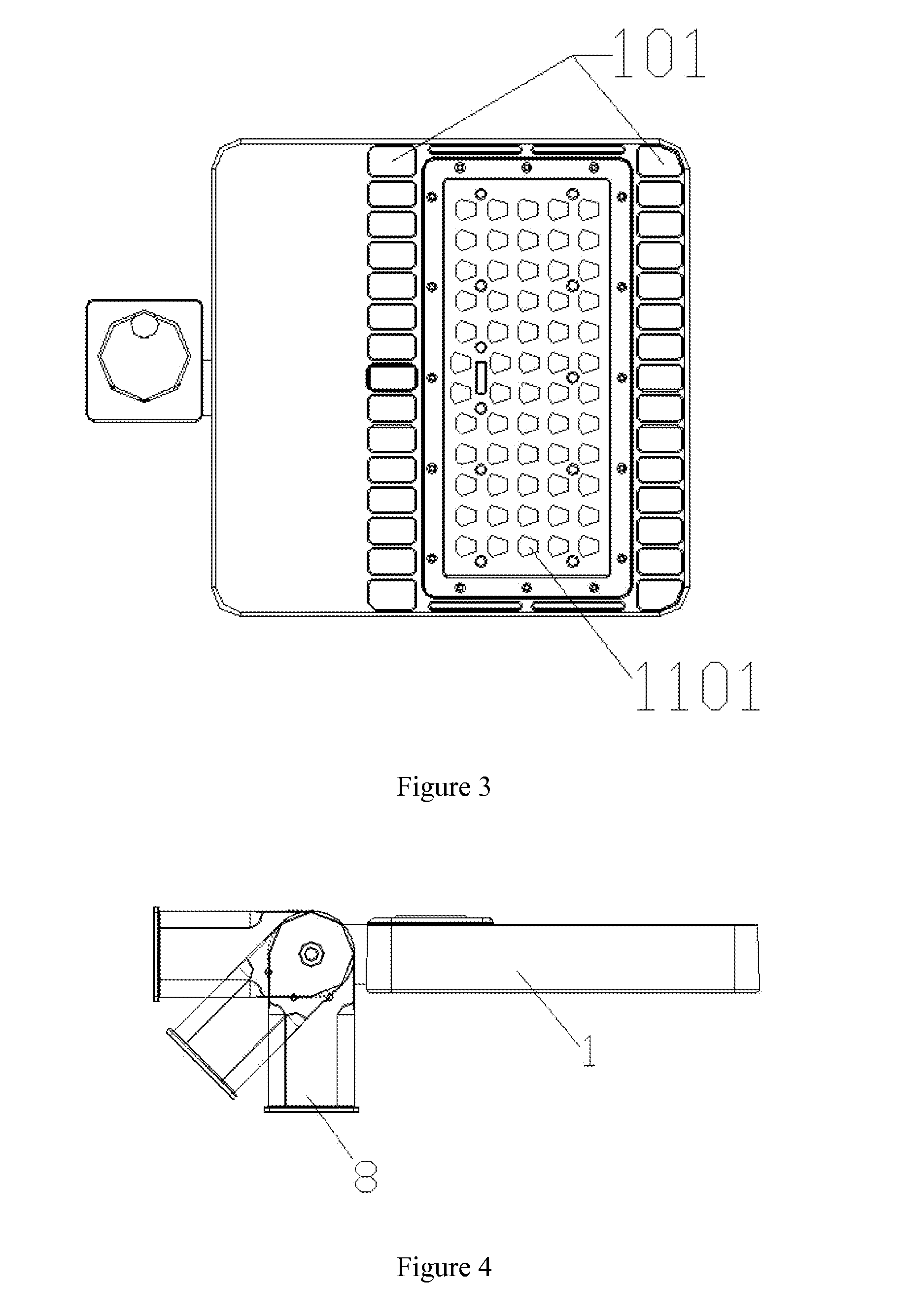
[0032]Please refer to FIG. 1, FIG. 2, FIG. 3 and FIG. 4, the invention Light Emitting Diode luminaire comprises radiator 1, power source 2, a plurality of Light Emitting Diode light sources 3, the power source 2 is connected with the Light Emitting Diode light sources 3 electrically; the power source 2 is installed on the radiator 1, and can be fixed by power strip 4, and covered by the cover of power box 5 and silicone ring of power box 6; the radiator 1 is equipped with through-holes 101 to make its top and bottom connected, forming air convection and facilitating air exchange, achieving good heat dissipation effect. The radiator 1 can have a number of heat sinks 102, with gaps between them, allowing for speedup of heat dissipation. The material of radiator 1 can be aluminum or copper etc., allowing for acceleration of heat dissipation.

[0033]The ...


PUM


Abstract

A kind of Light Emitting Diode (LED) luminaire comprises a radiator, a power source and a plurality of LED light sources. The power source is connected with the LED light sources electrically; the power source is installed on the radiator which is equipped with holes to make its top and bottom connected. The LED luminaire is equipped with an adapter assembly comprising a first adapter and a second adapter, which are rotatably and movably connected through a tooth profile structure. The first adapter is fixed on the radiator; when in use, the second adapter is fixed with the outside. The LED luminaire further comprises a lens module board, which is fixed on the bottom of the radiator, covers the LED light sources, and is sealed by a waterproof ring, with one lens covering one LED light source. The lens on the lens module board is a polarized distribution lens.

Description

CROSS REFERENCE TO RELATED APPLICATIONS[0001]The present application is the claims priority to Chinese Utility Model CN201420306371.8 filed on Jun. 9, 2014.TECHNICAL FIELD[0002]The present invention relates to the field of luminaire, specially relates to a kind of Light Emitting Diode (LED) luminaire.BACKGROUND ART[0003]The Light Emitting Diode (LED) luminaire in existence is not convenient for air convection, nor for timely discharge of hot-air, and heat dissipation effect is poor. In addition, the overall structure is fixed and it is not convenient to adjust the angle. Furthermore, the lenses of the LED luminaire in existence are individual ones, with the glass panel separating the lenses from the outside. Though the purpose of waterproofing is achieved, the structure is not simple.CONTENT OF THE INVENTION[0004]For the above mentioned defects, the invention aims to providing a kind of Light Emitting Diode luminaire with better heat dissipation effect, convenient for adjusting angl...

Claims


Application Information

Patent Timeline
Patent Type & Authority Applications(United States)
IPC IPC(8): F21V29/83F21V29/89F21V31/00F21V5/04F21V23/02
CPCF21V29/83F21V5/048F21Y2101/02F21V31/005F21V29/89F21V23/02F21V5/007F21V5/04F21V21/30F21Y2105/10F21Y2115/10
Inventor YU, HUANHUANYONG, YING
Owner SHENZHEN YAORONG TECH
Why Eureka
Try Eureka