Inspection Apparatus, Inspection Method, And Program

a technology of inspection apparatus and inspection method, applied in the direction of image enhancement, instruments, image data processing, etc., can solve the problems of difficult adjustment of control parameters, difficult for users to satisfy strict installation conditions, and not easy for users to instinctively see whether or not the inspection image is correct, etc., to achieve the effect of facilitating parameter setting

Active Publication Date: 2015-12-10
KEYENCE
View PDF11 Cites 20 Cited by
  • Summary
  • Abstract
  • Description
  • Claims
  • Application Information

AI Technical Summary

Benefits of technology

[0008]Therefore, an object of the present invention is to facilitate setting of a parameter at the time of generating an inspection image from an image acquired by using a photometric stereo principle.
[0010]According to the present invention, a luminance image and an inspection image which is used for inspection are switched and displayed, or these are simultaneously displayed, thereby allowing the user to instinctively see a result of adjustment of a parameter. This can facilitate the setting of a parameter at the time of generating an inspection image from an image acquired by using a photometric stereo principle.

Problems solved by technology

A visual inspection apparatus is often installed by a user, and it is difficult for the user to satisfy these strict installation conditions.
However, since an inspection image used for inspection in the inspection apparatus is an image generated from luminance images by computing, even when the luminance images are checked, it is not easy to instinctively see whether or not the inspection image is correct.
Therefore, even when only the inspection image is displayed, it may be difficult for the user to adjust the control parameter.

Method used


Image

  • Inspection Apparatus, Inspection Method, And Program
  • Inspection Apparatus, Inspection Method, And Program
  • Inspection Apparatus, Inspection Method, And Program

Examples


Embodiment Construction

[0043]Hereinafter, one embodiment of the present invention is shown. An individual embodiment described below will be useful for understanding a variety of concepts such as a superordinate concept, an intermediate concept, and a subordinate concept of the present invention. Further, a technical range of the present invention is defined by the claims, and is not limited by the following individual embodiment.

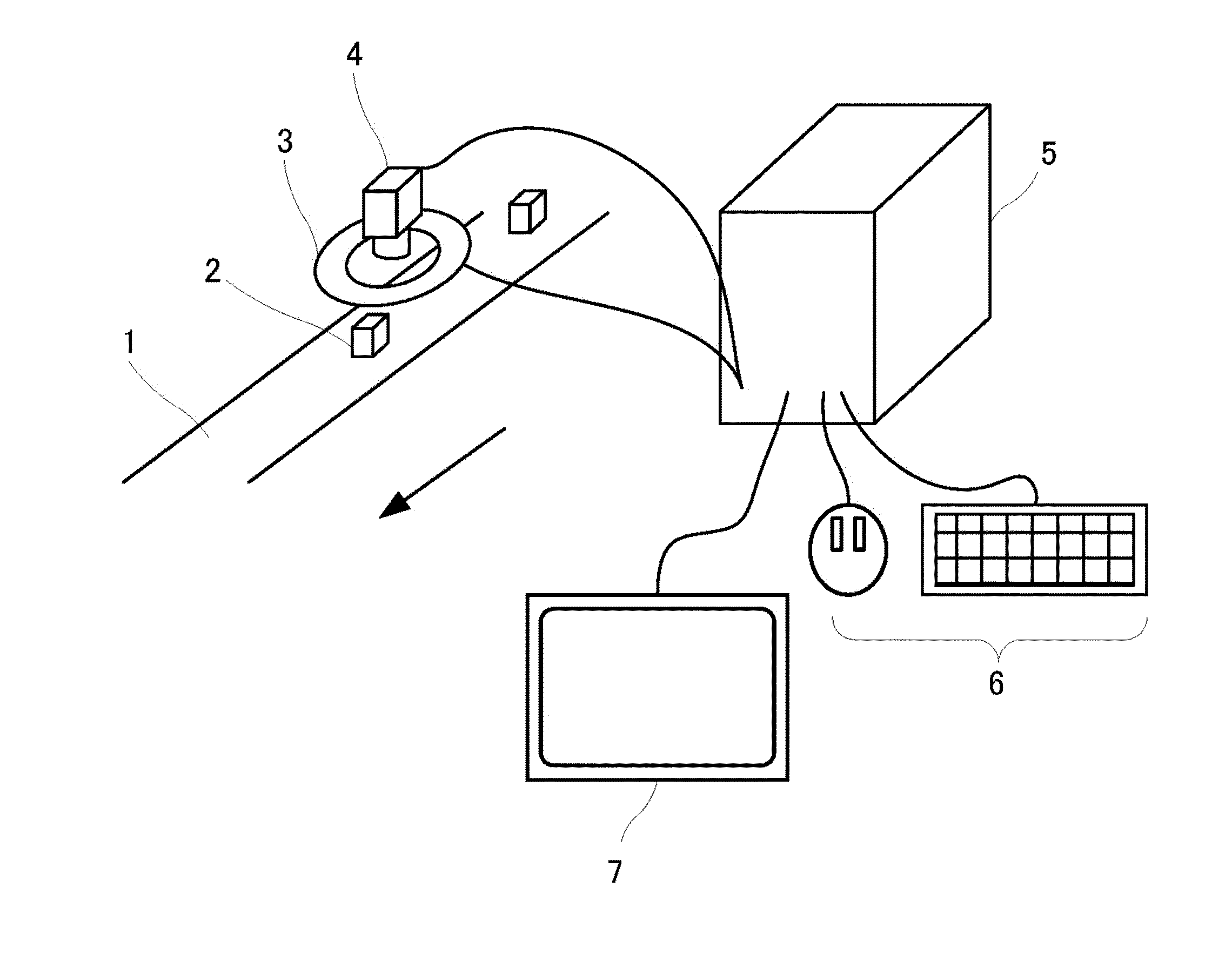
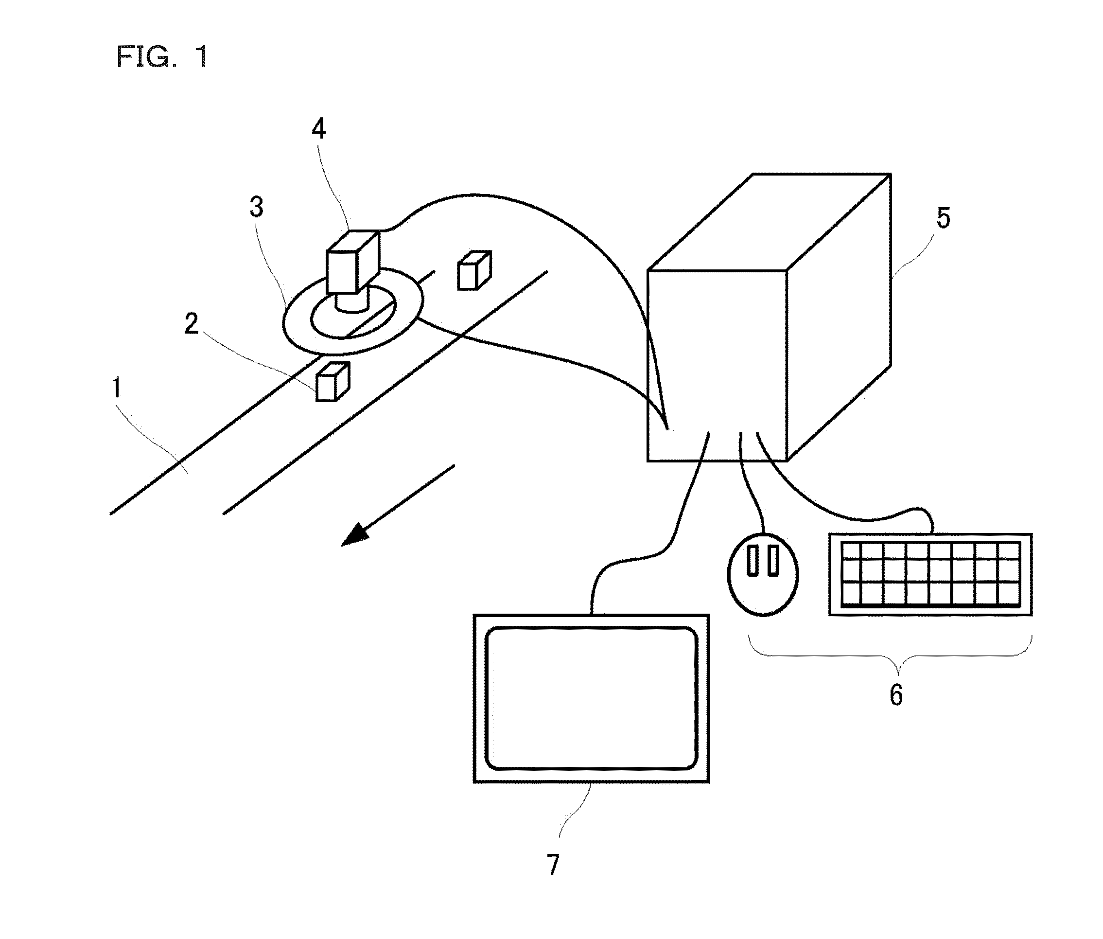
[0044]FIG. 1 is a view showing one example of a visual inspection system. A line 1 is a conveyer belt for conveying a workpiece 2 which is an inspection target. An illumination apparatus 3 is one example of an illumination section for illuminating an inspection target in accordance with a photometric stereo method. A camera 4 is one example of an imaging section for receiving reflective light from the illuminated inspection target to generate a luminance image in accordance with the photometric stereo method. An image processing apparatus 5 is a visual inspection apparatus for ca...


PUM

PropertyMeasurementUnit
luminanceaaaaaaaaaa
sizeaaaaaaaaaa
sizesaaaaaaaaaa

Abstract

To facilitate setting of a parameter at the time of generating an inspection image from an image acquired by using a photometric stereo principle. A photometric processing part generates an inspection image based on a plurality of luminance images acquired by a camera. A display control part and a display part switch and display the luminance image and the inspection image, or simultaneously display these images. An inspection tool setting part adjusts a control parameter of the camera and a control parameter of an illumination apparatus. Further, when the control parameter is adjusted, the display control part updates the image being displayed on the display part to an image where the control parameter after the change has been reflected.

Description

CROSS-REFERENCE TO RELATED APPLICATIONS[0001]The present application claims foreign priority based on Japanese Patent Application No. 2014-119100, filed Jun. 9, 2014, the contents of which is incorporated herein by reference.BACKGROUND OF THE INVENTION[0002]1. Field of the Invention[0003]The present invention relates to an inspection apparatus, an inspection method, and a program.[0004]2. Description of Related Art[0005]In order to measure an accurate three-dimensional shape of a workpiece (inspection target product) by using a photometric stereo principle, there is required an illumination light source whose illumination light is incident on each surface of the workpiece with a uniform light amount. Further, an angle of incidence of the illumination light is required to be known. Moreover, since the angle of incidence of light should not change in accordance with a region of the workpiece, there is required an illumination light source having a size corresponding to the size of the...

Claims


Application Information

Patent Timeline
Patent Type & Authority Applications(United States)
IPC IPC(8): G01N21/88G06T7/00H04N13/02
CPCG01N21/8806H04N13/0207G01N21/8803G06T2207/10152G01N2201/06G06T2207/30164G06T7/0004G01N21/8851G06T7/586G06T2207/20016G01N2201/061
Inventor ANDO, DAISUKE
Owner KEYENCE
Why Eureka
Try Eureka