Periphetal object detection system and haulage vehicle

a detection system and periphetal object technology, applied in the direction of distance measurement, instruments, using reradiation, etc., can solve the problems of high manufacturing cost of such unmanned dump trucks, and the above-described problem also arises in the same way in the manned dump trucks

Active Publication Date: 2015-12-10
NIHON KENKI CO LTD
View PDF9 Cites 26 Cited by
  • Summary
  • Abstract
  • Description
  • Claims
  • Application Information

AI Technical Summary

Problems solved by technology

Further, any attempt to apply the technology of JP2009-175932A as a technology for confirming areas forward and backward of the unmanned dump truck requires laser range finders for the confirmation of the areas forward and backward of the unmanned dump truck, so that the problem of higher manufacturing costs for such unmanned dump trucks remains unsolved.
Therefore, the above-described problem also arises in the manned dump truck in much the same way as in the unmanned dump truck.

Method used


Image

  • Periphetal object detection system and haulage vehicle
  • Periphetal object detection system and haulage vehicle
  • Periphetal object detection system and haulage vehicle

Examples


first embodiment

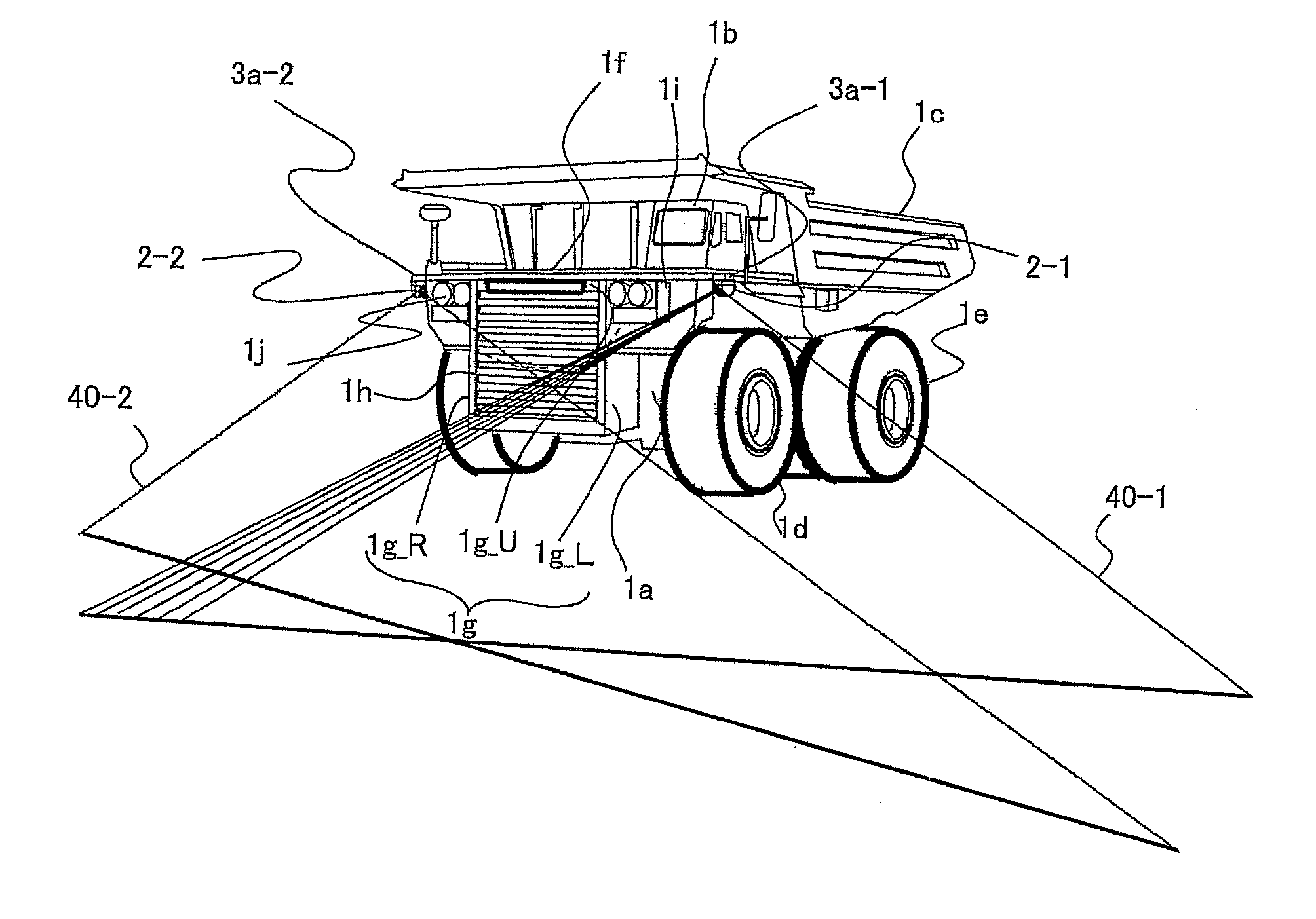
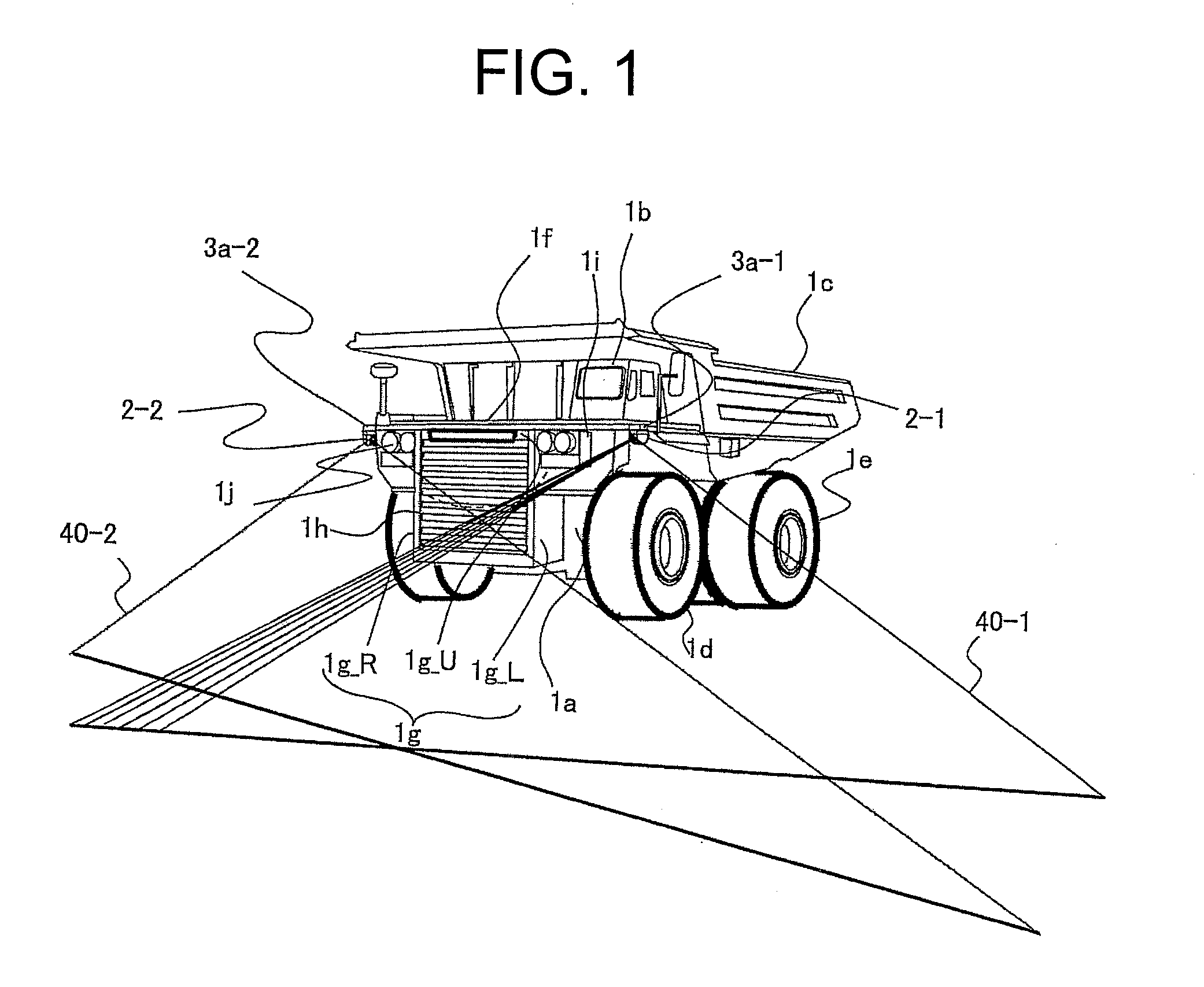
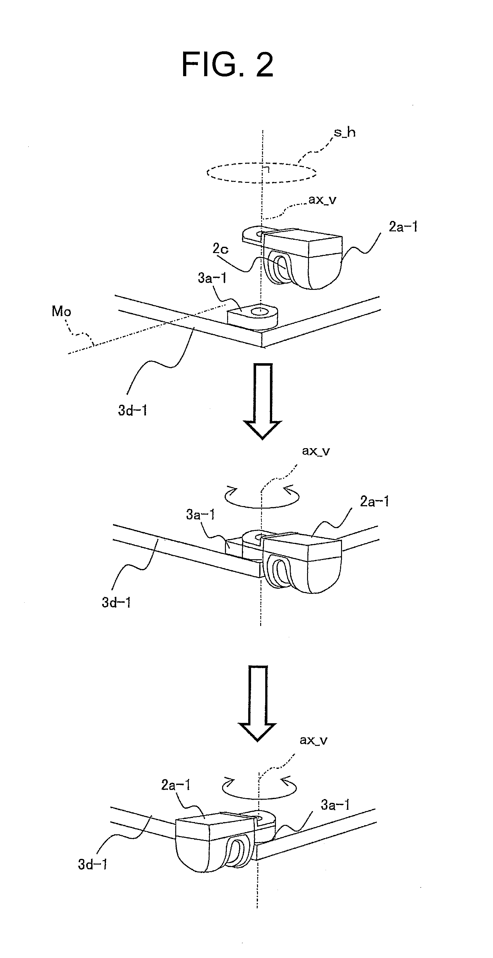
[0050]The first embodiment is an embodiment that switches to a forward monitoring state or a backward monitoring state depending on whether an unmanned dump truck 1 as a haulage vehicle is traveling forward or in preparation for traveling or is traveling in reverse. In addition, the first embodiment also includes an embodiment that during forward traveling, the position of a detecting range is displaced further forward. Referring first to FIGS. 1 and 2, a description will be made about an unmanned dump truck with a peripheral object detection system according to the first embodiment as mounted thereon and fixing structures for LIDAR sensors in the peripheral object detection system. FIG. 1 is a schematic configuration diagram of the unmanned dump truck with the peripheral object detection system according to the first embodiment being mounted thereon. FIG. 2 is a schematic perspective view illustrating the fixing structure for the LIDAR sensor and the manner of its operation for swi...

second embodiment

[0140]With reference to FIG. 19, a description will hereinafter be made about a second embodiment of the present invention. FIG. 19 is a schematic plan view illustrating the detecting ranges (scanplanes 40-1,40-2) of LIDAR sensors 2 in a peripheral object detection system according to the second embodiment as mounted on an unmanned dump truck 1.

[0141]The second embodiment is different from the above-described first embodiment in that for the adjustment of the scan planes 40-1,40-2 of the LIDAR sensors 2-1,2-2, the platforms 3a-1,3a-2 are rotated according only to the time of switching of an area, such as the dumping site, travel path or the like, and the traveling speed in the first embodiment while the platforms 3a-1,3a-2 are rotated according to the steering angle in addition to the time of switching of the area and the traveling speed in the second embodiment. About the second embodiment, a description will hereinafter be made with reference to the functional block diagram of FIG...

third embodiment

[0143]With reference to FIGS. 20 and 21, a description will hereinafter be made about a third embodiment of the present invention. FIG. 20 is a diagram illustrating a position of intersection of scan planes in a forward monitoring state in the third embodiment. FIG. 21 is a schematic plan view illustrating scan planes by laser irradiation and reception modules in a peripheral object detection system according to the third embodiment of the present invention as mounted on an unmanned dump truck. The third embodiment is different from the above-described first embodiment in that the scan planes 40-1,40-2 of the LIDAR sensors 2-1,2-2 are allowed to intersect each other in the area forward of the unmanned dump truck 1 in the first embodiment while such scan planes 40-1,40-2 are allowed to intersect each other at a position diagonally forward of an unmanned dump truck 1 and closer to a shoulder B as illustrated in FIG. 20.

[0144]In the third embodiment, reference information is stored in ...


PUM


Abstract

Disclosed is a peripheral object detection system to be mounted on a vehicle. The peripheral object detection system includes a peripheral information acquisition device and a detecting range switching mechanism. The peripheral information acquisition device is configured to have, as a detected range, apart of a peripheral space of the vehicle and to acquire distance information to an object that exists in the detected range and is to be detected. The detecting range switching mechanism is configured to switch, toward an area forward or backward of the vehicle, a direction of a detecting range of the peripheral information acquisition device based on forward/backward information that indicates whether the vehicle is moving in a forward direction or in a reverse direction.

Description

CROSS-REFERENCE TO RELATED APPLICATION[0001]This application claims the priority of Japanese Patent Application 2014-116017 filed Jun. 4, 2014, which is incorporated herein by reference.BACKGROUND OF THE INVENTION[0002]1. Field of the Invention[0003]This invention relates to a peripheral object detection system and a haulage vehicle, and especially to a technology that makes it possible to reduce the number of parts and components used in peripheral monitoring surroundings of such a haulage vehicle.[0004]2. Description of the Related Art[0005]In so-called open-pit mining that rock and ore are excavated and delivered at the bottom of a mine, each haulage vehicle (hereinafter called “dump truck”) repeats operation that upon completion of loading of excavated rock, it hauls the excavated rock from the excavation site to a dumping site and dumps the excavated rock there, and travels back again to the excavation site. The haulage rate per unit time of rock, which is hauled by each dump t...

Claims


Application Information

Patent Timeline
Patent Type & Authority Applications(United States)
IPC IPC(8): G01S17/93G01S17/931
CPCG01S17/936G01S7/4813G01S7/4972G01S17/931G05D2201/021G05D1/024
Inventor ONO, YUKIHIKOISHIMOTO, HIDEFUMIFUJITA, KOJI
Owner NIHON KENKI CO LTD
Why Eureka
Try Eureka