Method to form a rail joint, and a rail joint
- Summary
- Abstract
- Description
- Claims
- Application Information
AI Technical Summary
Benefits of technology
Problems solved by technology
Method used
Image

Examples
Embodiment Construction
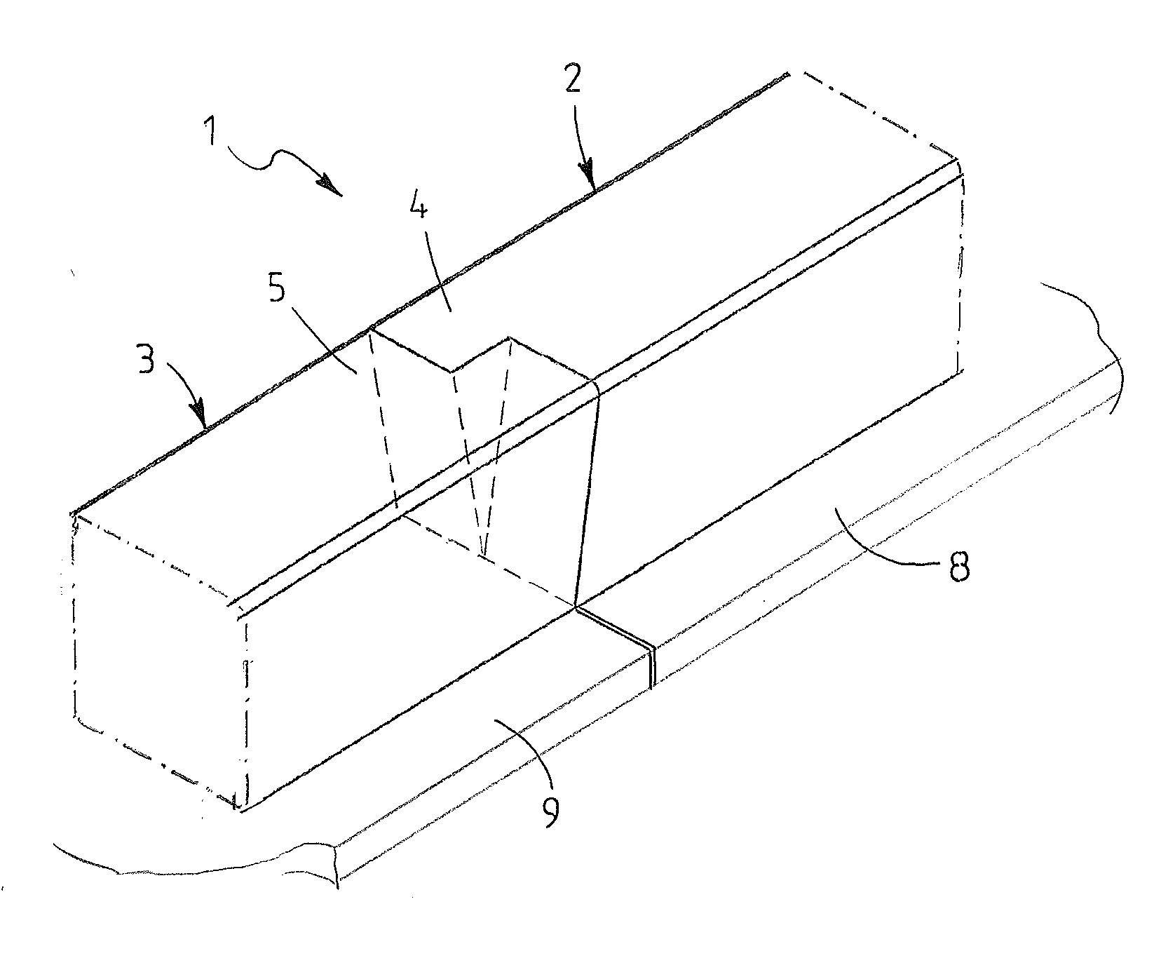
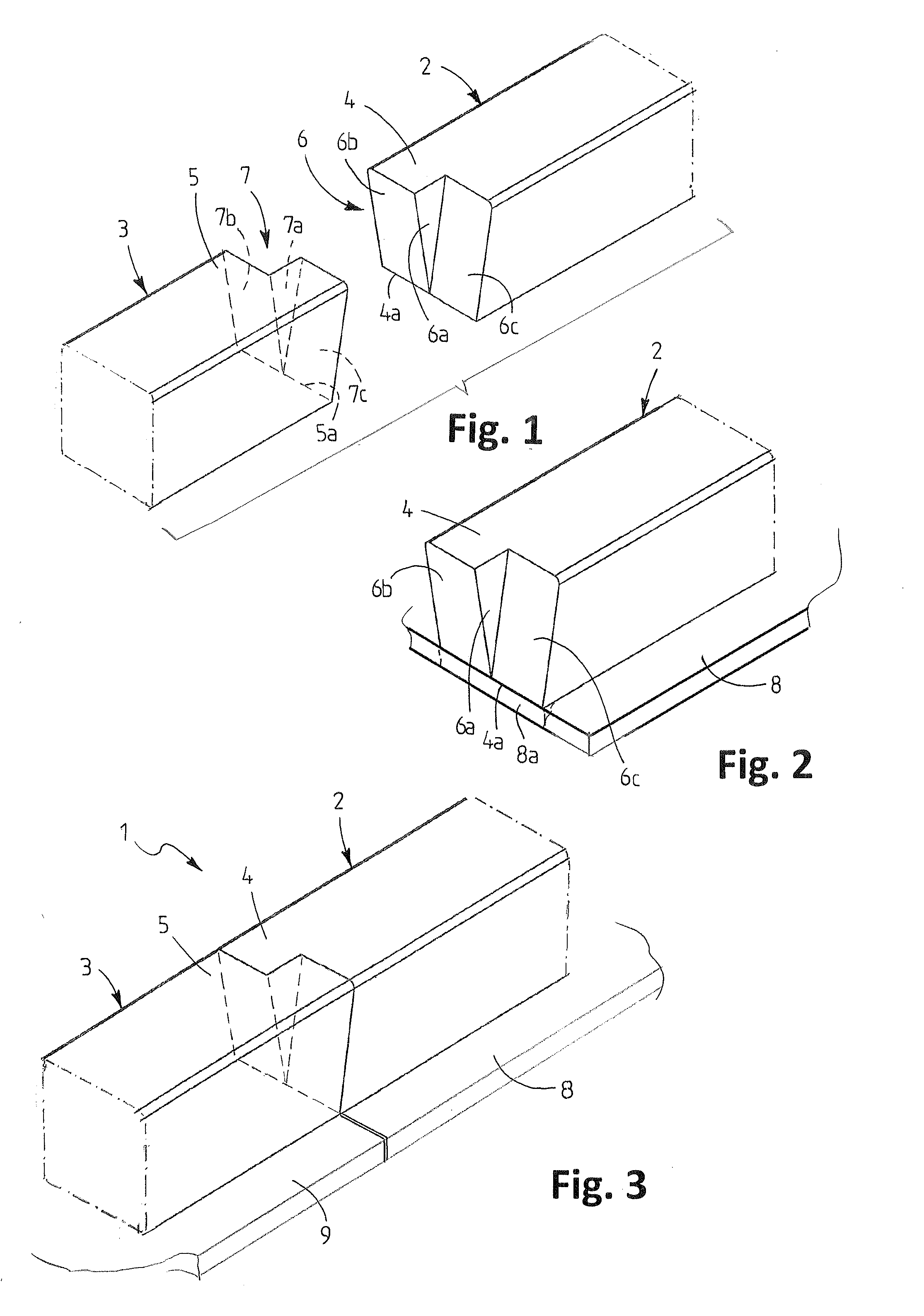
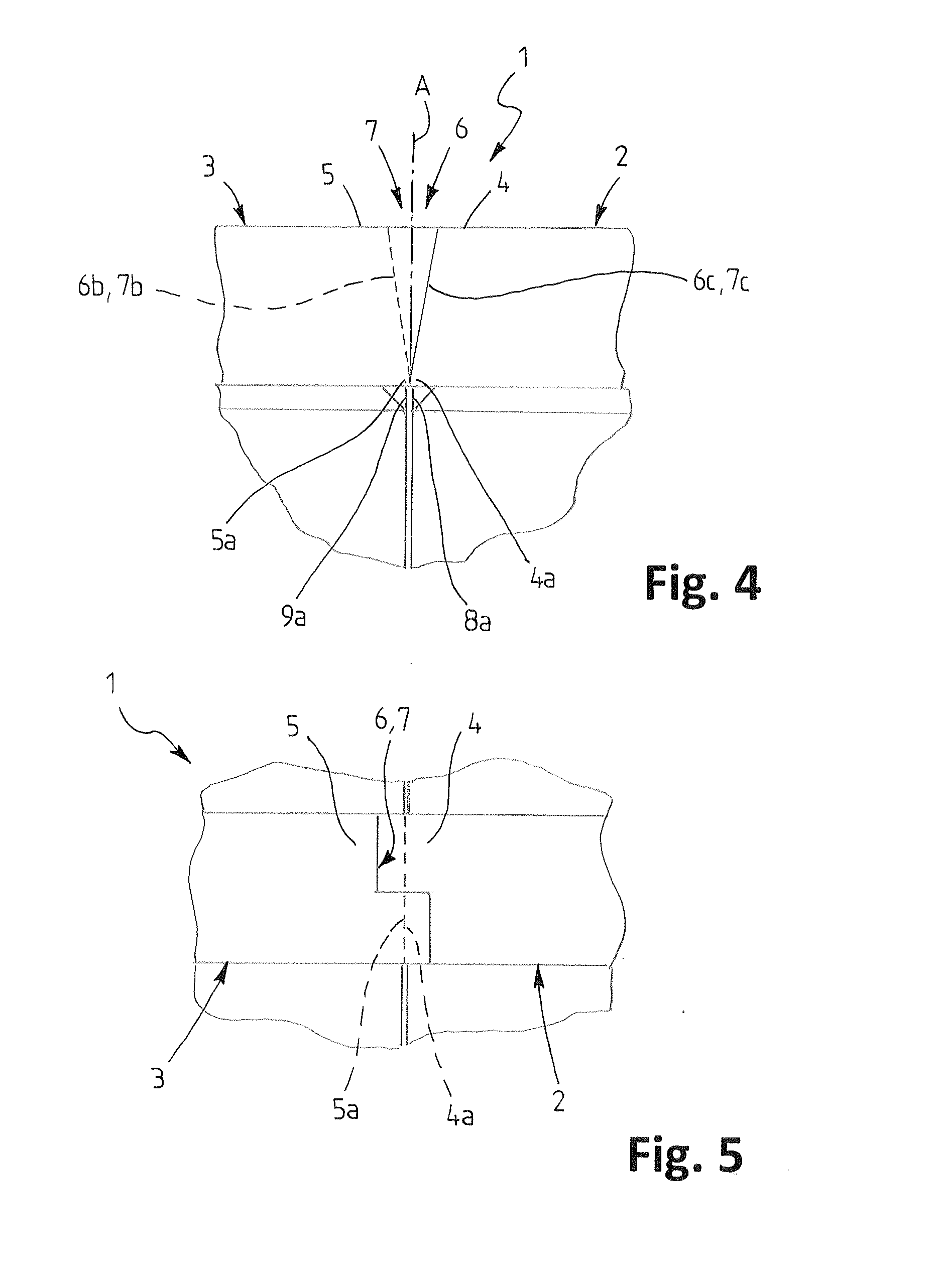
[0017]With reference to the drawings, the rail joint according to the invention is formed between solid profile rail ends 4 and 5 to be joined in parts 2 and 3 in a rail 1. The joint comprises staggerings 6, 7 corresponding to each other and connected to each other in a shape-locked manner in the rail ends 4 and 5 which are opposite each other and to be joined, so formed that in a completed rail joint, as seen from above, the rail ends 4 and 5 bond.
[0018]Instead, the lower edges 4a and 5a of the rail ends are substantially unstaggered, and the staggerings 6 and 7 extend from these substantially unstaggered lower edges 4a and 5a of the rail ends 4 and 5 in the direction of the top surfaces of the rail ends 4 and 5.
[0019]The rail ends 4 and 5 are welded by their lower edges 4a and 5a at their entire width to the end edges 8a and 8b of the mountings 8 and 9, the end edges being located in the same vertical plane with the lower edges of the rail ends 4 and 5, and, with a bolted joint be...
PUM
 Abstract
Description
Claims
Application Information
 - R&D Engineer
- R&D Manager
- IP Professional
- Industry Leading Data Capabilities
- Powerful AI technology
- Patent DNA Extraction
Browse by: Latest US Patents, China's latest patents, Technical Efficacy Thesaurus, Application Domain, Technology Topic.
© 2024 PatSnap. All rights reserved.Legal|Privacy policy|Modern Slavery Act Transparency Statement|Sitemap