
Vehicle lamp fitting

a technology for lamps and fittings, applied in fixed installations, lighting and heating equipment, instruments, etc., can solve problems such as appearance degradation and light not radiating, and achieve the effect of suppressing appearance degradation

Active Publication Date: 2015-12-17
ICHIKOH IND LTD
View PDF17 Cites 12 Cited by
  • Summary
  • Abstract
  • Description
  • Claims
  • Application Information

AI Technical Summary

Benefits of technology

The invention aims to provide a vehicle lamp fitting that maintains consistent lighting and prevents appearance issues.

Problems solved by technology

However, in the case of a light guide provided at both ends with a light source, the light intensity is greater in regions in which light guided from both ends overlaps and is emitted, compared with other regions, and light does not radiate uniformly, and thus the appearance deteriorates.

Method used


Image

  • Vehicle lamp fitting
  • Vehicle lamp fitting
  • Vehicle lamp fitting

Examples


Embodiment Construction

[0020]A mode of embodying the present invention (hereinafter referred to as embodiment) will now be described in detail with reference to the accompanying drawings. It should be noted that the same numbers are appended to elements that are the same throughout the entire description of the embodiment.

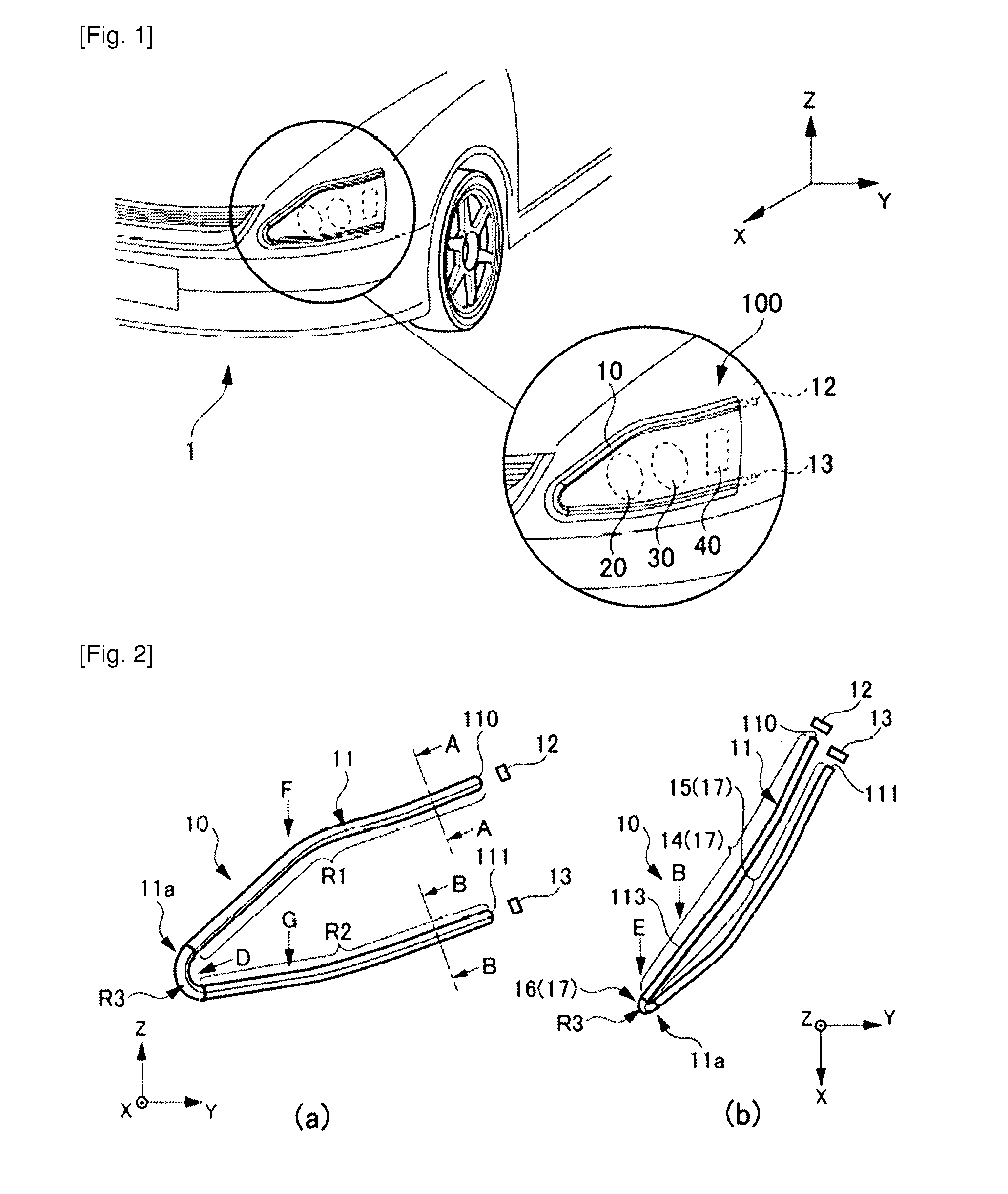
[0021]FIG. 1 is an enlarged schematic view of the area in the vicinity of a headlamp 100 according to an embodiment applying the present invention. FIG. 1 illustrates the front portion of a vehicle 1, with a further enlarged illustration of the area in the vicinity of the headlamp 100. Directions X, Y and Z are illustrated in FIG. 1, coinciding respectively with the forward direction of the vehicle 1, the width direction of the vehicle 1 and the height direction of the vehicle 1. The X, Y and Z directions are also illustrated as necessary in the subsequent drawings.

[0022]As illustrated in FIG. 1, the headlamp 100 comprises a clearance lamp 10 in the form of a vehicle lamp fitting, a high...


PUM


Abstract

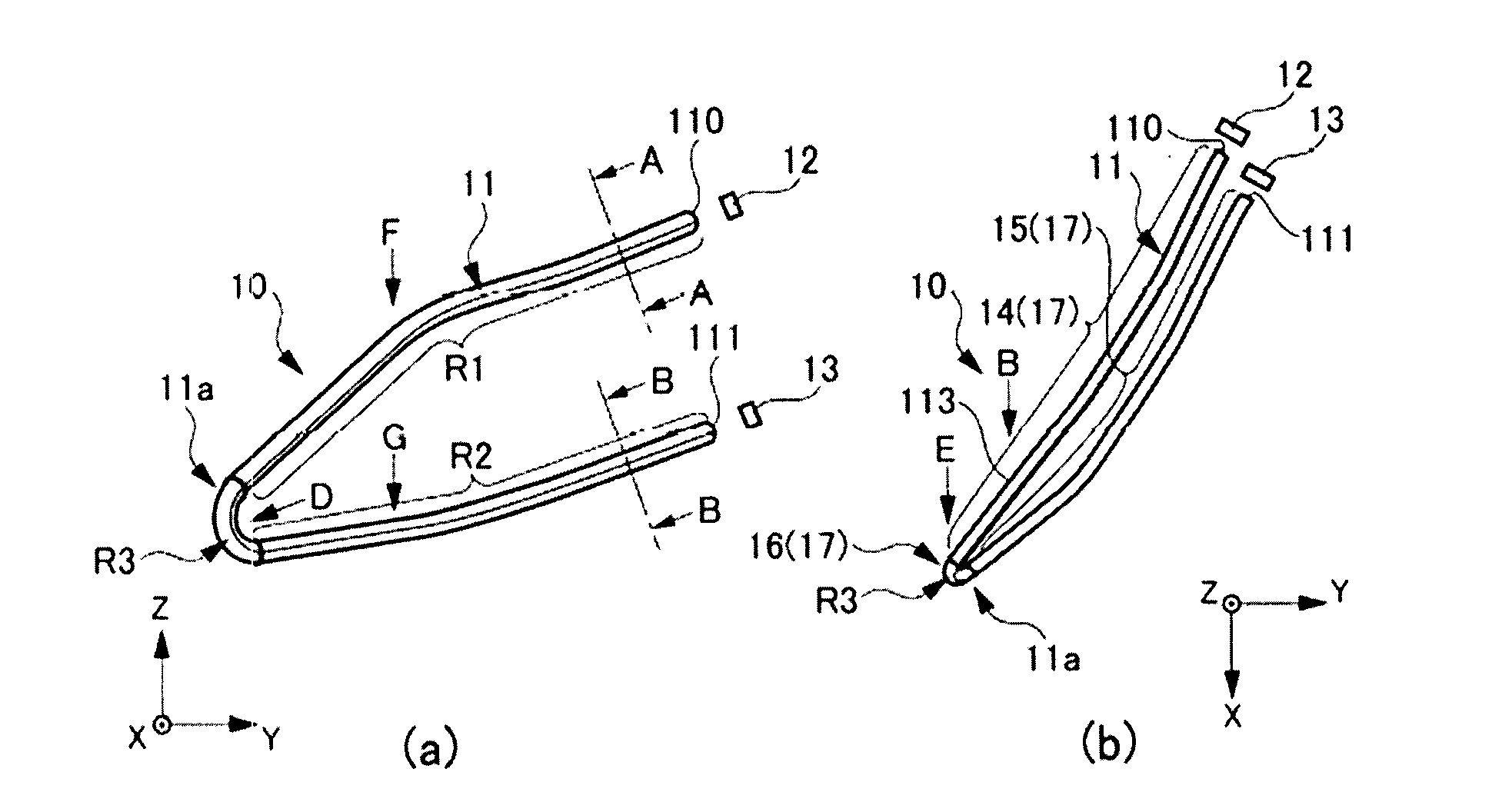
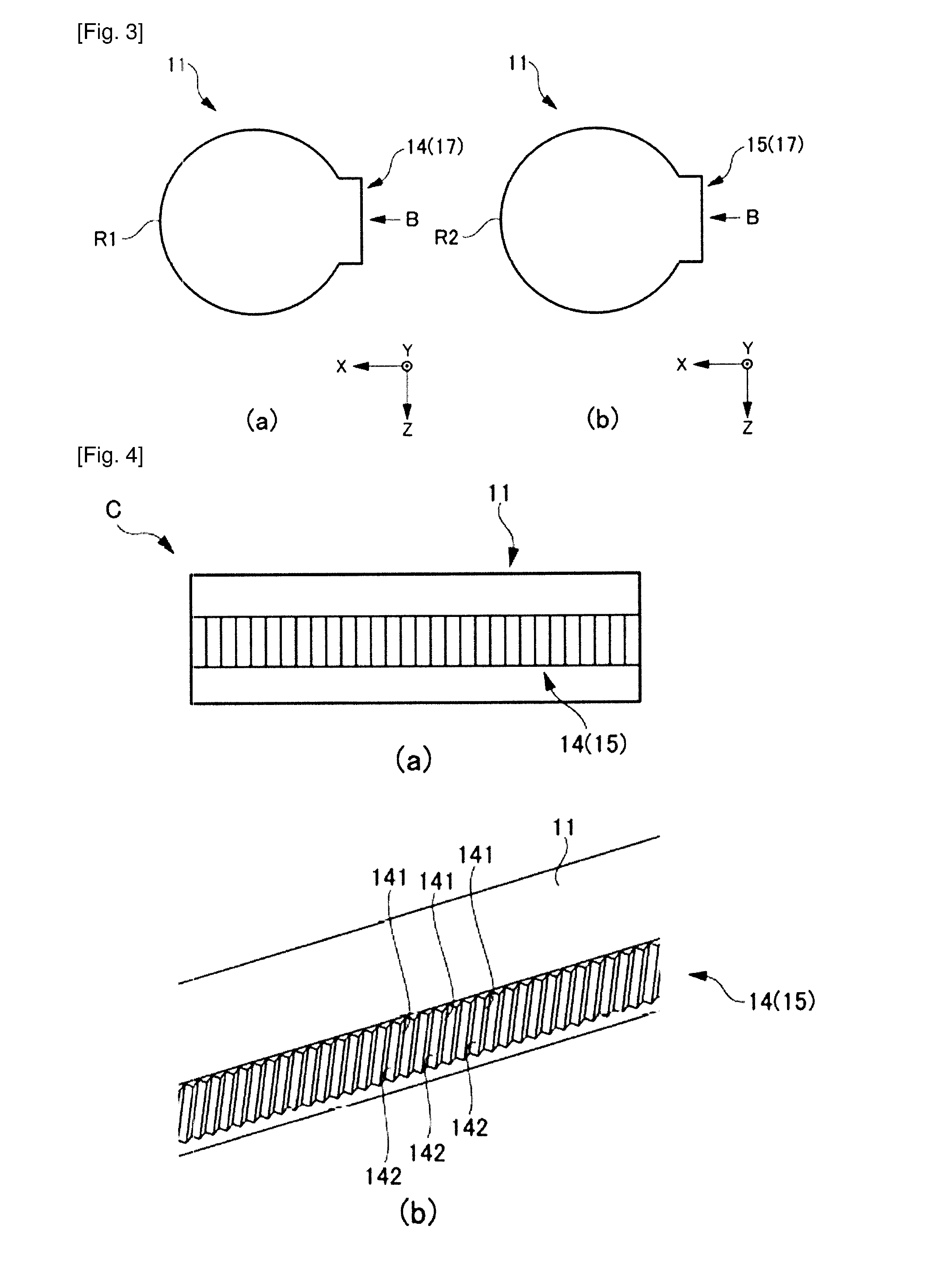
Problem: To provide a vehicle lamp fitting in which regularity of the strength or weakness of the emitted light is maintained and deterioration of appearance is suppressed. Solution: A vehicle lamp fitting 10 comprises a light guide 11 which guides light from an LED light source 12 and an LED light source 13, the light guide 11 having entrance surfaces 110, 111, emission surfaces R1 to R3, and an internally reflecting surface 17 which causes light that has entered through the entrance surfaces 110, 111 to be reflected, and the internally reflecting surface 17 comprises a reflecting surface 141 which is provided in a first region 14 and which emits light from the LED light source 12 in a forward direction, a reflecting surface 151 which is provided in a second region 15 and which emits light from the LED light source 13 in the forward direction, and a reflecting surface 161 which is formed in a third region 16 between the first region 14 and the second region 15 and which limits the light intensity with which light from the LED light sources 12, 13 is emitted in the forward direction from the emission surface R3.

Description

TECHNICAL FIELD[0001]The present invention relates to a vehicle lamp fitting.BACKGROUND ART[0002]In terms of known vehicle lamp fittings there are those which are provided with an[0003]LED (Light Emitting Diode) light source, which serves as a light source, and a light guide. In a light guide, a plurality of reflecting prisms having two reflecting surfaces are formed (see for example JP 2007-109654 A).[0004]There are also known vehicle lamp fittings in which light sources are provided at both ends of a light guide, and light from each of the light sources is controlled by altering the angles of the two reflecting surfaces of a plurality of reflecting prisms provided in neighboring contact from both ends of the light guide, and is emitted from an emitting portion (for example JP 2011-198537 A and JP 2011-216279 ASUMMARY OF INVENTIONProblem to be Resolved by the Invention[0005]However, in the case of a light guide provided at both ends with a light source, the light intensity is great...

Claims


Application Information

Patent Timeline
Patent Type & Authority Applications(United States)
IPC IPC(8): F21V8/00F21S8/10
CPCG02B6/0055F21S48/115F21Y2101/02G02B6/0035F21S48/1241F21S43/237F21S43/249F21S43/14F21S43/245B60Q1/0052G02B6/0038F21Y2115/10F21W2103/10F21S41/24
Inventor NISHIHATA, KOUJIMATSUMURA, GENTAHAYASHI, HIDEYUKI
Owner ICHIKOH IND LTD
Learn More