Method and device for dynamically switching gateway of distributed resilient network interconnect

a resilient network and dynamic switching technology, applied in data switching networks, instruments, frequency-division multiplexes, etc., can solve the problems of not defining the problem, unable to meet the demand of node protection, and limited protection technology of the loop network

Inactive Publication Date: 2015-12-17
ZTE CORP
View PDF3 Cites 13 Cited by
  • Summary
  • Abstract
  • Description
  • Claims
  • Application Information

AI Technical Summary

Benefits of technology

[0009]The embodiment of the present invention provides a method and apparatus for dynamically switching a gatewa

Problems solved by technology

The loop network protection technology is limited by the network topology, and it is not applicable to adopting the whole network connection mode for the network interconnection part.
In the current standard 802.1AX of the Institute of Electrical and Electronics Engineers (IEEE), the link aggregation can realize the protection of multiple links, but only limited to the link aggregation supporting the single node, which cannot satisfy the demand of the node protection.
However, the standard does not def

Method used


Image

  • Method and device for dynamically switching gateway of distributed resilient network interconnect
  • Method and device for dynamically switching gateway of distributed resilient network interconnect
  • Method and device for dynamically switching gateway of distributed resilient network interconnect

Examples


application example one

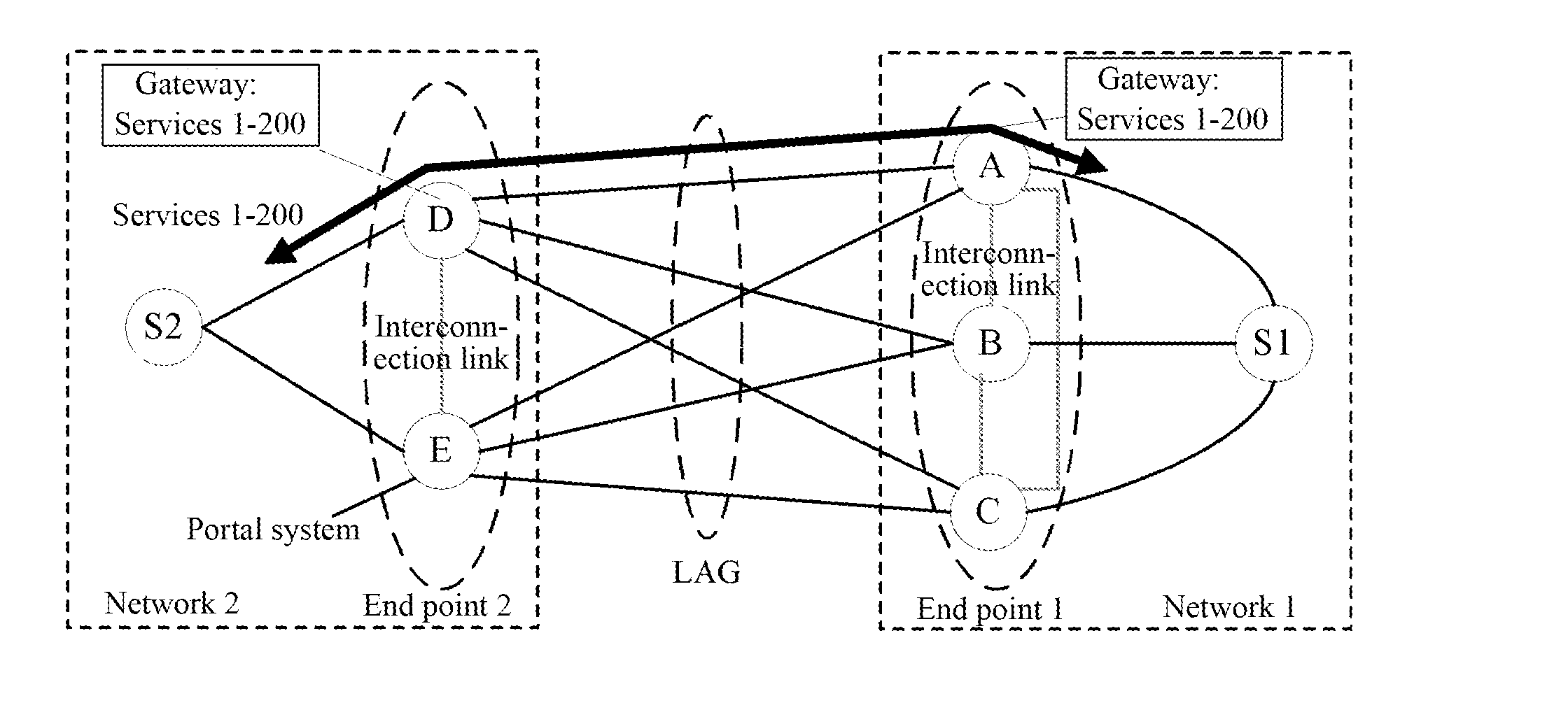
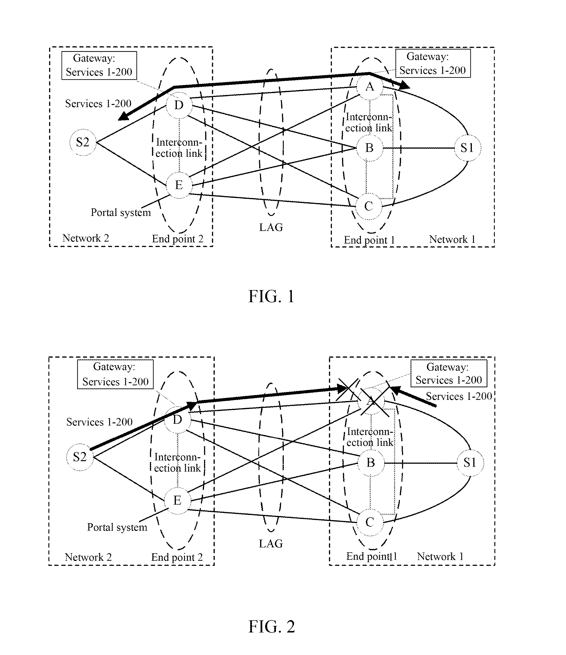
[0093]As shown in FIG. 7, the end point 1 of the aggregation group in network 1 is made up of 3 portal systems A, B and C, and the gateway of the portal system A is the gateway of the services 1-200, wherein the services 1-100 select the portal system with the high portal system priority as the portal system in which the backup gateway is located, that is, Select Algorithm=02; the services 101-200 adopt the average distribution method to select the portal system in which the backup gateway is located, that is, Select Algorithm=03. The gateway of the portal system B is the gateway of the services 201-300, and the gateway of the portal system C is the gateway of the services 301-400, the portal system with the high portal system priority is selected as the portal system in which the backup gateway is located, that is, Select Algorithm=02. The priority of the portal system A is 01, the priority of the portal system B is 02, and the priority of the portal system C is 03, that is, the pr...

application example two

[0111]The difference between the application example one and the application example two is, in the present embodiment, the backup gateway select algorithm announced among the portal systems can be the coding information of priority sequential list of the backup portal system through the configuration or according to the algorithm. The gateway of the available portal system of which the value of Backup Priority is small (that is, the backup priority is high) in the Backup gateway List is selected as the first-selected gateway of the Service List when the main gateway breaks down.

[0112]As shown in FIG. 12, the end point 1 of the aggregation group in network 1 is made up of 3 portal systems A, B and C, and the portal system A is the gateway of the services 1-200, wherein the backup gateway priority sequence of the services 1-100 is the portal systems B and C, and the backup gateway priority sequence of the services 101-200 is the portal systems C and B. The portal system B is the gate...


PUM


Abstract

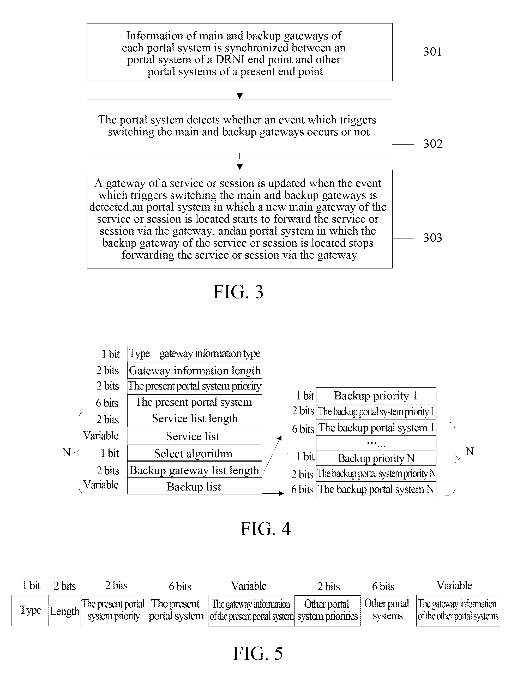
A method and apparatus for dynamically switching a gateway of a DRNI are provided. The method includes: synchronizing information of main and backup gateways of each portal system between a portal system of a DRNI end point and other portal systems of the present end point; the portal system detecting whether an event which triggers switching the main and backup gateways occurs or not; and updating a gateway of a service or session when the event which triggers switching the main and backup gateways is detected, a portal system in which a new main gateway of the service or session is located starting to forward the service or session via the main gateway, and a portal system in which the backup gateway of the service or session is located stopping forwarding the service or session via the backup gateway.

Description

TECHNICAL FIELD[0001]The present invention relates to the network communication protection technology, and in particular, to a method and apparatus for dynamically switching a gateway in distributed resilient network interconnect (DRNI).BACKGROUND OF THE RELATED ART[0002]With the development at full speed of the broadband service, the interconnection among the networks is used more and more, to bear more services. According to the adopted technology, there can be many kinds of methods to realize protecting the links and the nodes thereon inside the network. As the protection demand to the flowrate being stronger and stronger and the requirement being higher and higher, some operators put forward the demand of requiring to protect the network interconnection area as well. The protection can be realized by adopting the port aggregation or loop mode. The loop network protection technology is limited by the network topology, and it is not applicable to adopting the whole network connect...

Claims


Application Information

Patent Timeline
IPC IPC(8): H04L12/703H04L12/891H04L12/709H04L45/243H04L45/28H04L47/41
CPCH04L45/28H04L47/41H04L45/245H04L45/00
Inventor XU, XUEQIONGYU, JINGHAIGUO, ZHUI
Owner ZTE CORP
Why Eureka
Try Eureka