High resiliency network intrastructure

a network intrastructure and high-resiliency technology, applied in the field of communication networks, can solve the problems of insufficient scalability, add to the creation of bottlenecks, reduce the average bandwidth available to each station on the link, etc., and achieve the effect of reducing processing delays of data traffic, high degree of resiliency, reliability and scalability

Inactive Publication Date: 2009-03-05
VERIZON PATENT & LICENSING INC
View PDF17 Cites 10 Cited by
  • Summary
  • Abstract
  • Description
  • Claims
  • Application Information

AI Technical Summary

Benefits of technology

[0019]The invention provides a highly resilient network infrastructure that provides connectivity between a main network such as the Internet and a subnetwork such as a server-based (e.g., web server) local area network. In accordance with the invention, a network interface incorporated into a server hosting center provides a resilient architecture that achieves redundancy in each of three different layers of the Open System Interconnect (OSI) stack protocol (i.e., physical interface, data link, and network layers). For every network device that is active as a primary communication tool for a group of subnetworks, the same device is a backup for another group of subnetworks. Based on the same connection-oriented switching technology (e.g., asynchronous transfer mode (ATM)) found in high-speed, broadband Internet backbones such as that provided by Internet MCI, the network interface architecture provides a high degree of resiliency, reliability and scalability.
[0020]In accordance with the invention, interface network routers which provide routing functionality and connectivity between the Internet backbone and the customer subnetworks are fully meshed with those deployed in the Internet backbone. Permanent virtual circuits (PVCs) providing a multitude of logical transmission paths between each hosting center router and every router in the Internet backbone, greatly reduces processing delays of data traffic through the infrastructure as only a single “hop” routing step is required between any external access point on the Internet backbone and a hosting center router.

Problems solved by technology

The disadvantage of such protocols is that the addition of more stations on the link reduces the average bandwidth available to each station on the link.
Adding customer subnets and routers to satisfy increase in usage, therefore, only adds to the bottlenecks created by the insufficient scalability (i.e., ability to provide adequate solutions with increase in size) of the interface architecture in the hosting center 310.
The failure along the transmission path between customer subnet routers 36c and 36e would be catastrophic for at least some of these customers.
Moreover, because the Ethernet segments connecting the components in the interface architecture must be bridged together in a loop-free topology, redundant paths cannot be created between bridged Ethernet segments.
The lack of resiliency inherent in this architecture contributed to Internet blackouts and slowdowns that occurred often and added delay for data packets to reach their destinations to and from the hosting center.

Method used


Image

  • High resiliency network intrastructure
  • High resiliency network intrastructure
  • High resiliency network intrastructure

Examples


Embodiment Construction

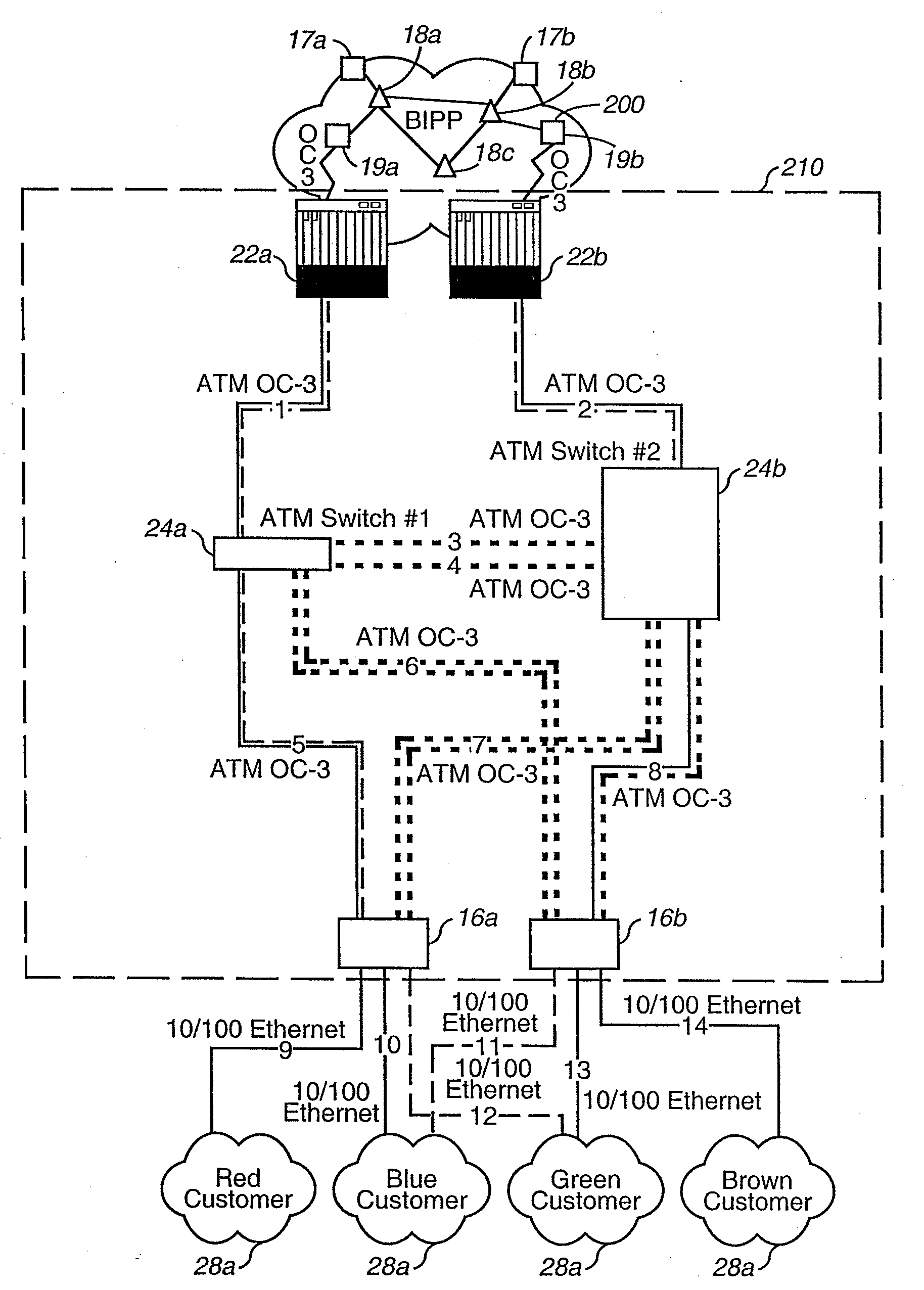
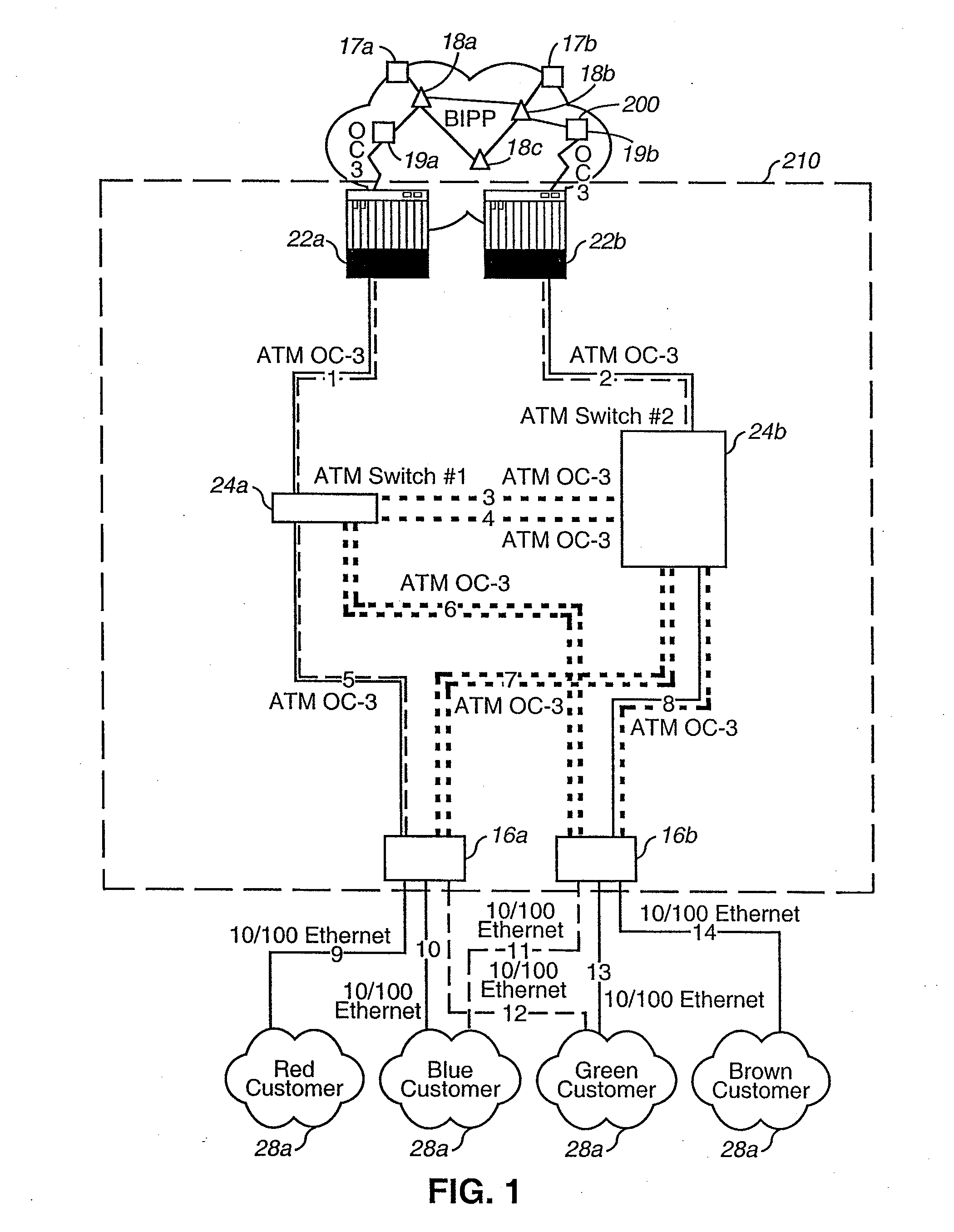
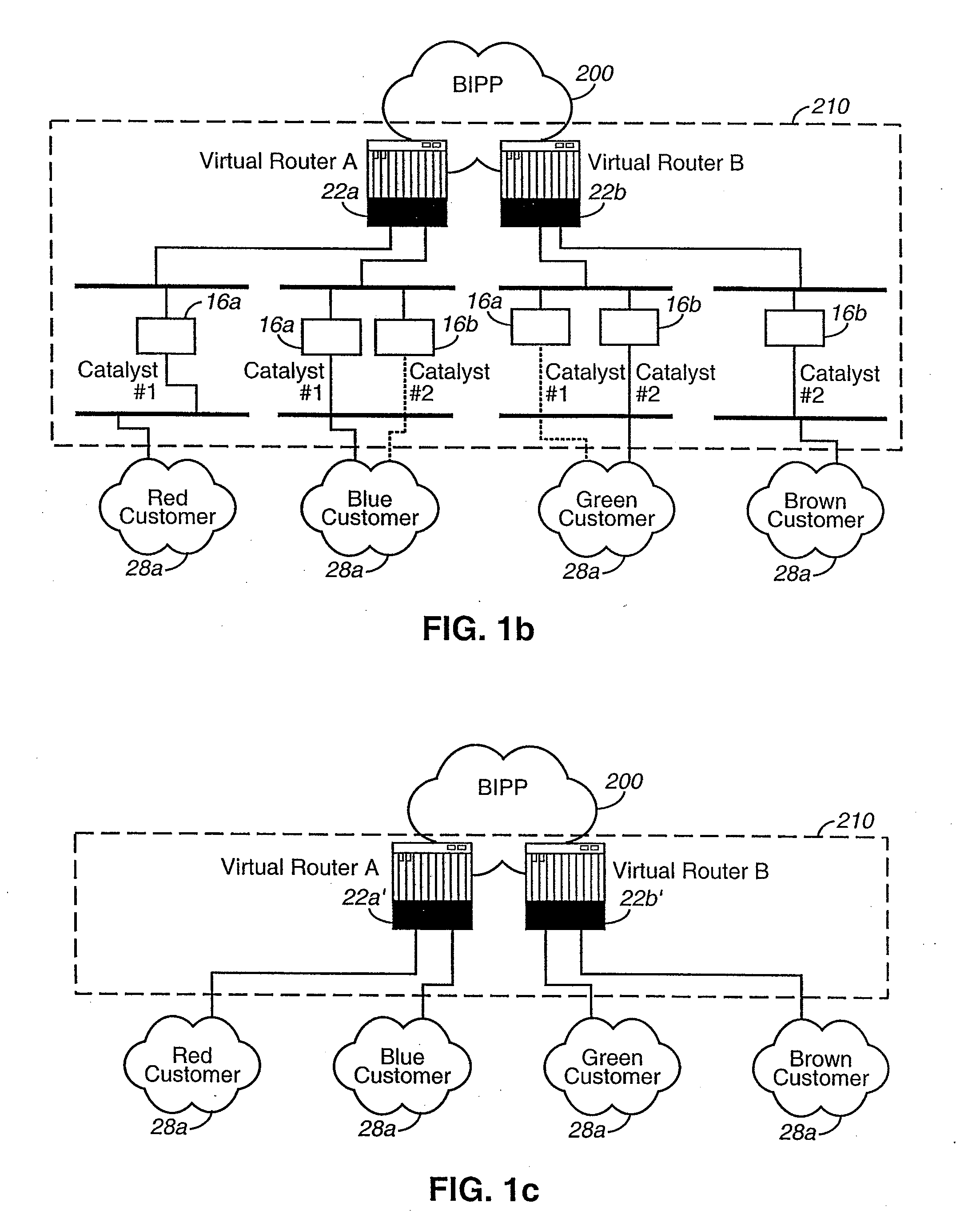
[0028]The invention will be described in detail with reference to the preferred embodiments illustrated in FIGS. 1a, 1b, 1c, 2a, 2b, and 3. The invention is described herein in its preferred application to a hosting network infrastructure that provides hosting services to customer subnetworks to allow the subnetworks to transfer information to and from an Internet backbone network. However, the invention may be applicable to any type or configuration of communications network that provides connectivity between a subnetwork and a main network.

[0029]As shown in FIG. 1a, in accordance with a preferred embodiment of the invention, a hosting center 210 provides a highly resilient, redundant, and scaleable infrastructure supplying connectivity between a customer (via customer subnetwork 28a) and the Internet (via Internet backbone 200). In the preferred embodiment, the customer subnetworks 28a may be LANs having local servers for one or more of a variety of applications, including web ser...


PUM


Abstract

A resilient interface architecture may include at least two interface switches and at least two interface routers. The at least two interface switches may provide connectivity between a subnetwork and a main network. If one of the switches fails, the connectivity otherwise provided by the failed interface switch may be provided by another one of the interface switches. Each interface router may be individually coupled to at least one interface switch. The interface routers may select a transmission path between the subnetwork and the main network through the interface switches. If one of the interface routers fails, the selection of transmission paths otherwise provided by the failed interface router may be provided by another one of the interface routers.

Description

BACKGROUND OF THE INVENTION[0001]The invention relates to the field of communication networks. More specifically, the invention relates to improving resiliency, scalability, and efficiency in the infrastructure of a network.[0002]The increased popularity of and reliance on the Internet has made the Internet the ultimate computer network. Millions of users around the world access the Internet for personal as well as business use daily. The Internet, however, is not really a specific network at all, but rather an amorphous mass of interconnected networks spanning the globe while utilizing the same Internet Protocol (IP) to pass information from one network to another. The networks making up the Internet are typically arranged in groups of computers connected together to allow information to be transmitted to one another. Such groups are referred to as “local area networks (LAN).” The LAN medium is “connectionless,” i.e., users on the LAN exchange message information without building s...

Claims


Application Information

Patent Timeline
Patent Type & Authority Applications(United States)
IPC IPC(8): H04L12/26G06F11/00H04L12/56H04L12/28G01R31/08
CPCH04L12/5601H04L45/10H04L2012/5618H04L49/309H04L45/586
Inventor PHALTANKAR, KAUSTUBH
Owner VERIZON PATENT & LICENSING INC
Why Eureka
Try Eureka