Stator body centering feature for torque converter

a technology of torque converter and torque converter body, which is applied in the direction of fluid coupling, gas turbine, liquid fuel engine, etc., can solve the problems of time-consuming and difficult process

Inactive Publication Date: 2015-12-24
SCHAEFFLER TECH AG & CO KG
View PDF4 Cites 9 Cited by
  • Summary
  • Abstract
  • Description
  • Claims
  • Application Information

AI Technical Summary

Benefits of technology

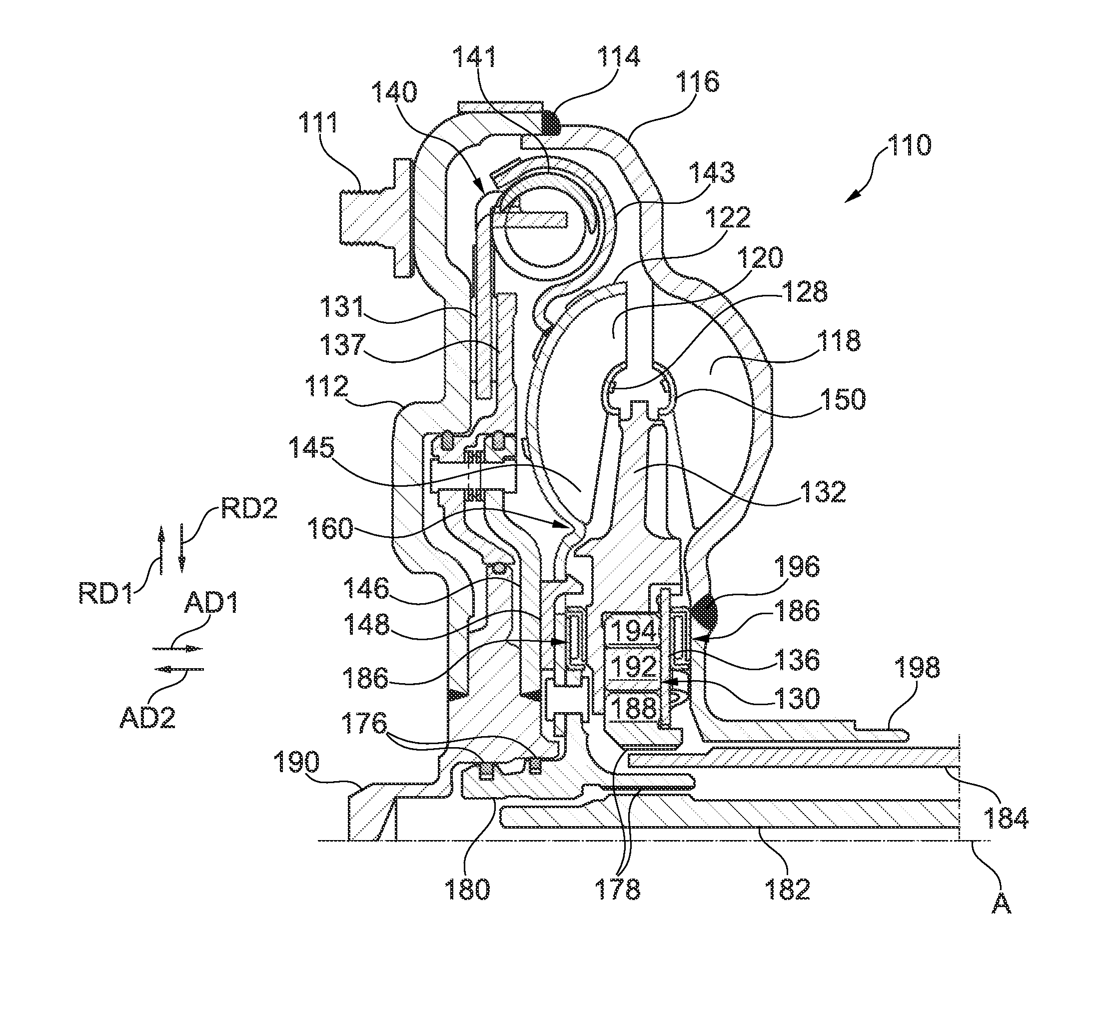
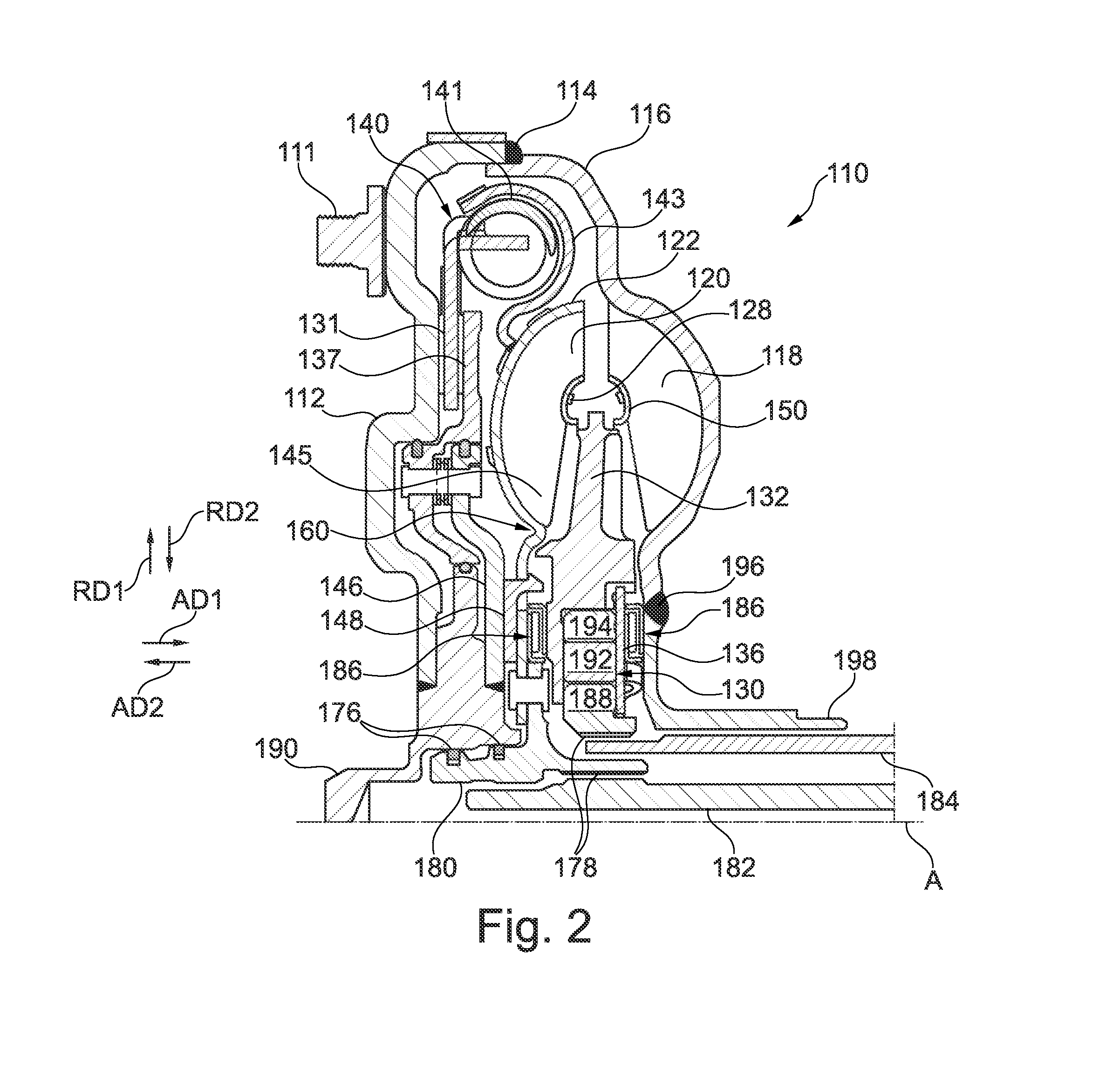
[0009]In an example aspect, the turbine's curved portion limits axial and radial displacement of the stator's centering protrusion. In an example aspect, the at least one centering protrusion is for maintaining concentricity relative to the axis of rotation and for limiting displacement of the stator within the turbine shell. In an example aspect, the at least one centering protrusion is annular. In other example aspects, the at least one centering protrusion is a plurality of castles. In an example aspect, the castles are cylindrical, cuboid, or frustum shaped. In an example aspect, the at least one centering protrusion is arranged to fit complementarily within the inner periphery portion of the turbine shell.

Problems solved by technology

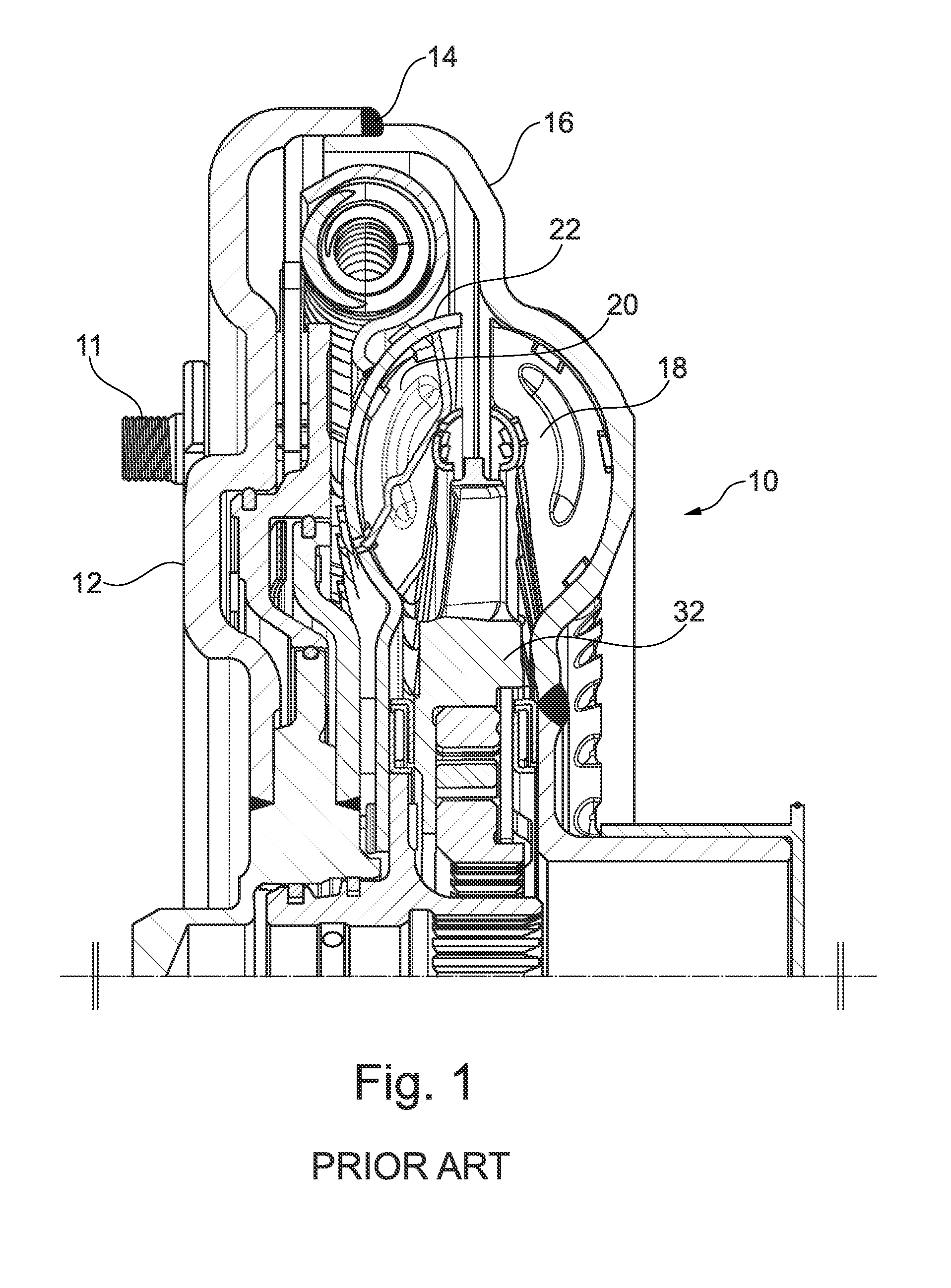
This process can be difficult and time consuming because of the large number of shafts and hubs that must be properly aligned.

Method used


Image

  • Stator body centering feature for torque converter
  • Stator body centering feature for torque converter
  • Stator body centering feature for torque converter

Examples


Embodiment Construction

[0016]At the outset, it should be appreciated that like drawing numbers appearing in different drawing views identify identical, or functionally similar, structural elements.

[0017]Furthermore, it is understood that this invention is not limited only to the particular embodiments, methodology, materials and modifications described herein, and as such may, of course, vary. It is also understood that the terminology used herein is for the purpose of describing particular aspects only, and is not intended to limit the scope of the present invention, which is limited only by the appended claims.

[0018]Unless defined otherwise, all technical and scientific terms used herein have the same meaning as commonly understood to one of ordinary skill in the art to which this invention belongs. Although any methods, devices or materials similar or equivalent to those described herein can be used in the practice or testing of the invention, the following example methods, devices, and materials are n...


PUM


Abstract

A stator for a torque converter comprising: (i) an axis of rotation; (ii) a body portion including: a first body circumference; a back wall; at least one centering protrusion extending to a first measured axial distance relative to the back wall; and a second body circumference; (iii) a blade portion including: an outer circumference; and a plurality of blades, arranged for directing fluid flow, extending in a radial direction from the second body circumference to the outer circumference; and (iv) a housing portion, disposed radially inward relative to the body portion, including: a radial wall, disposed at a second measured axial distance relative to the back wall, having a thrust surface; and, wherein the housing portion is arranged for housing a one-way clutch; and, wherein the first axial distance is greater than the second axial distance.

Description

FIELD[0001]The invention relates generally to a stator in a torque converter, and more specifically to a stator having at least one centering feature, which mates complementarily with the turbine shell, to position the stator during assembly.BACKGROUND[0002]Co-pending U.S. Provisional Patent Application No. 61 / 899,325, hereby incorporated by reference herein, describes a torque converter, and shows a core ring featuring tabs or lances to center the stator.[0003]U.S. Pat. No. 8,573,374, hereby incorporated by reference herein, discloses a method for centering a hub flange for a torque converter, wherein the stator inner race is centered on the pump hub inner diameter.[0004]U.S. Patent Application Publication No. 2012 / 0266589, hereby incorporated by reference herein, discloses a torque converter cross-section including a turbine including at least one blade and a shell, wherein the shell includes a portion disposed radially inward of the at least one blade.[0005]To install a torque co...

Claims


Application Information

Patent Timeline
Patent Type & Authority Applications(United States)
IPC IPC(8): F01D9/04F16H45/02F01D25/24F16H41/04F01D5/02F01D5/12
CPCF01D9/041F01D5/02F01D5/12F05D2240/14F16H41/04F16H45/02F01D25/24F16H41/24F16H2045/021F16H2045/0221F16H2045/0294
Inventor SMITH, MATTHEWSAYRE, DANIEL
Owner SCHAEFFLER TECH AG & CO KG
Why Eureka
Try Eureka