Stereomicroscope having a main observer beam path and a co-observer beam path

a stereomicroscope and beam path technology, applied in the field of surgical microscopes, can solve the problems of increasing complexity, inability to produce co-observer beam paths, and inability to have other co-observer positions, so as to reduce the distance between the outer lenses of the zoom system, reduce the lens diameter, and free the effect of orientation selection

Active Publication Date: 2015-12-24
CARL ZEISS MEDITEC AG
View PDF9 Cites 9 Cited by
  • Summary
  • Abstract
  • Description
  • Claims
  • Application Information

AI Technical Summary

Benefits of technology

[0010]In comparison with the prior art described in the introduction, the use of the geometrical beam splitter enables the beam emerging from the main objective to be split between the main observer beam path and the co-observer beam path in each case without loss of light for the stereoscopic partial beam paths. In addition, the use of a large co-observer zoom system makes it possible to select the orientation of the coupling-out and thus the orientation of the co-observer relative to the main observer even downstream of the co-observer zoom system, without the zoom system having to be rotated. In this case, the selection of the orientation can be carried out, for example, via a suitably oriented reflector disposed downstream of the co-observer zoom system. The invention therefore makes it possible to produce a flexibly usable surgical microscope in which the orientation of the co-observer can be defined even after the passage of the co-observer beam through the zoom system wherein, on account of the fact that no physical beam splitter need be used, no appreciable loss of light arises either for the main observer or for the co-observer. The high flexibility can therefore be achieved without losses in the image quality. Overall, the ergonomics of the stereomicroscope are increased as a result. Moreover, the use of a respective dedicated zoom system for the main observer beam path and for the co-observer beam path affords the advantage that the magnification is individually settable for main observer and co-observer.
[0019]In one particular embodiment of the stereomicroscope according to the invention, in the co-observer beam path there is a splitter for separating the stereoscopic partial beams of the co-observer beam path. An intermediate imaging system is then arranged between the co-observer zoom system and the splitter, which intermediate imaging system images the device pupil of the co-observer beam path onto an input end of the splitter. The intermediate imaging system can include in particular a first converging lens or a first converging lens system, a second converging lens or a second converging lens system, and an intermediate image plane situated between the first converging lens or the first converging lens system and the second converging lens or the second converging lens system. The imaging of the device pupil onto the input end of the splitter makes it possible to avoid vignetting in the co-observer beam path.

Problems solved by technology

Other co-observer positions are not possible in the case of the co-observer beam paths.
However, since this co-observer beam path is already coupled out in front of the main objective of the main observer beam path, it necessitates a dedicated main objective, which increases the complexity and, in association therewith, the production costs for the co-observer beam path.
In addition, the beam splitter arranged between the observation object and the main objective results in loss of light in the main observer beam path and thus in a reduction of the image quality for the main observer.
This results in loss of light in the main observer beam path and thus in a reduction of the image quality for the main observer.

Method used


Image

  • Stereomicroscope having a main observer beam path and a co-observer beam path
  • Stereomicroscope having a main observer beam path and a co-observer beam path
  • Stereomicroscope having a main observer beam path and a co-observer beam path

Examples


Embodiment Construction

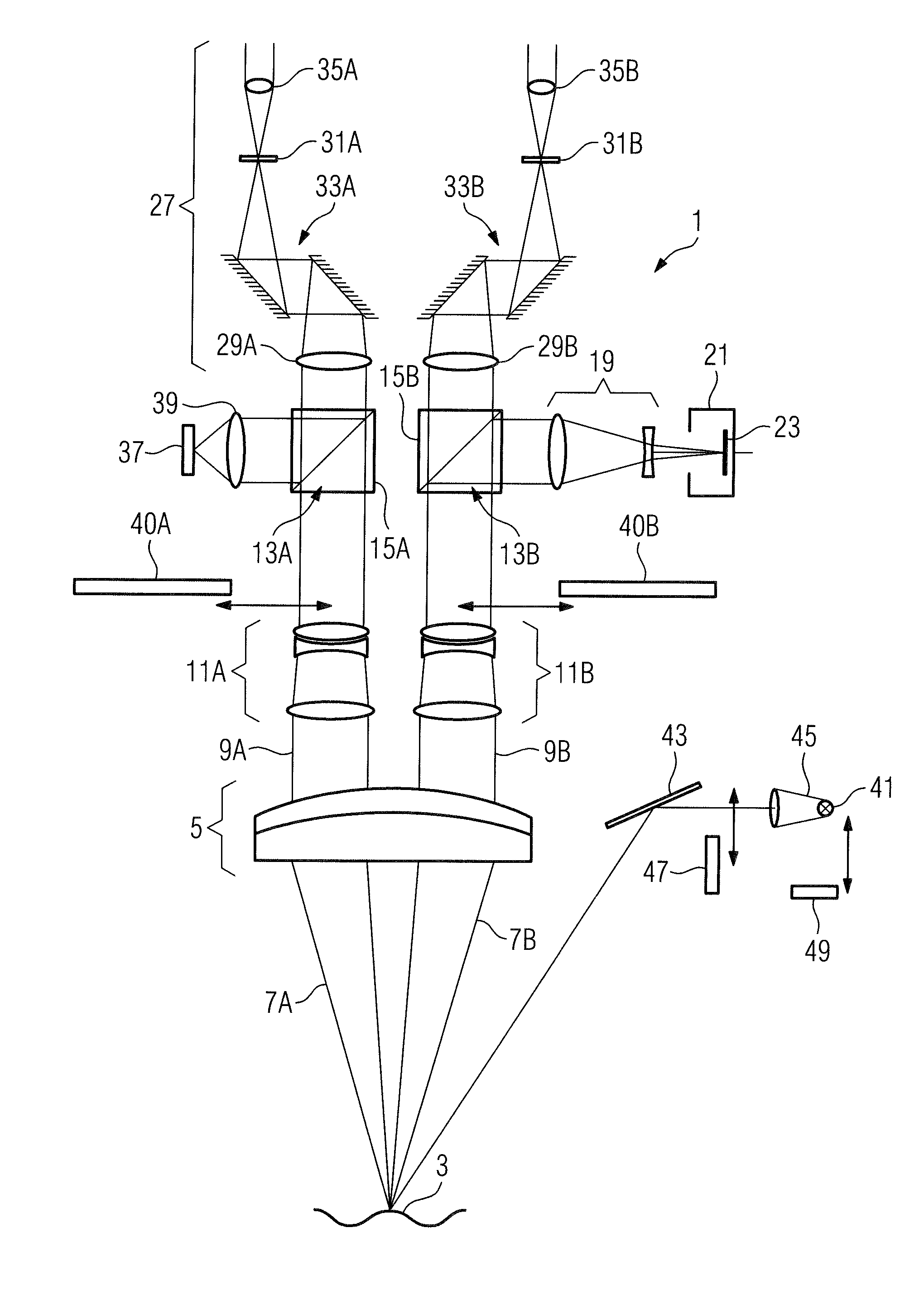
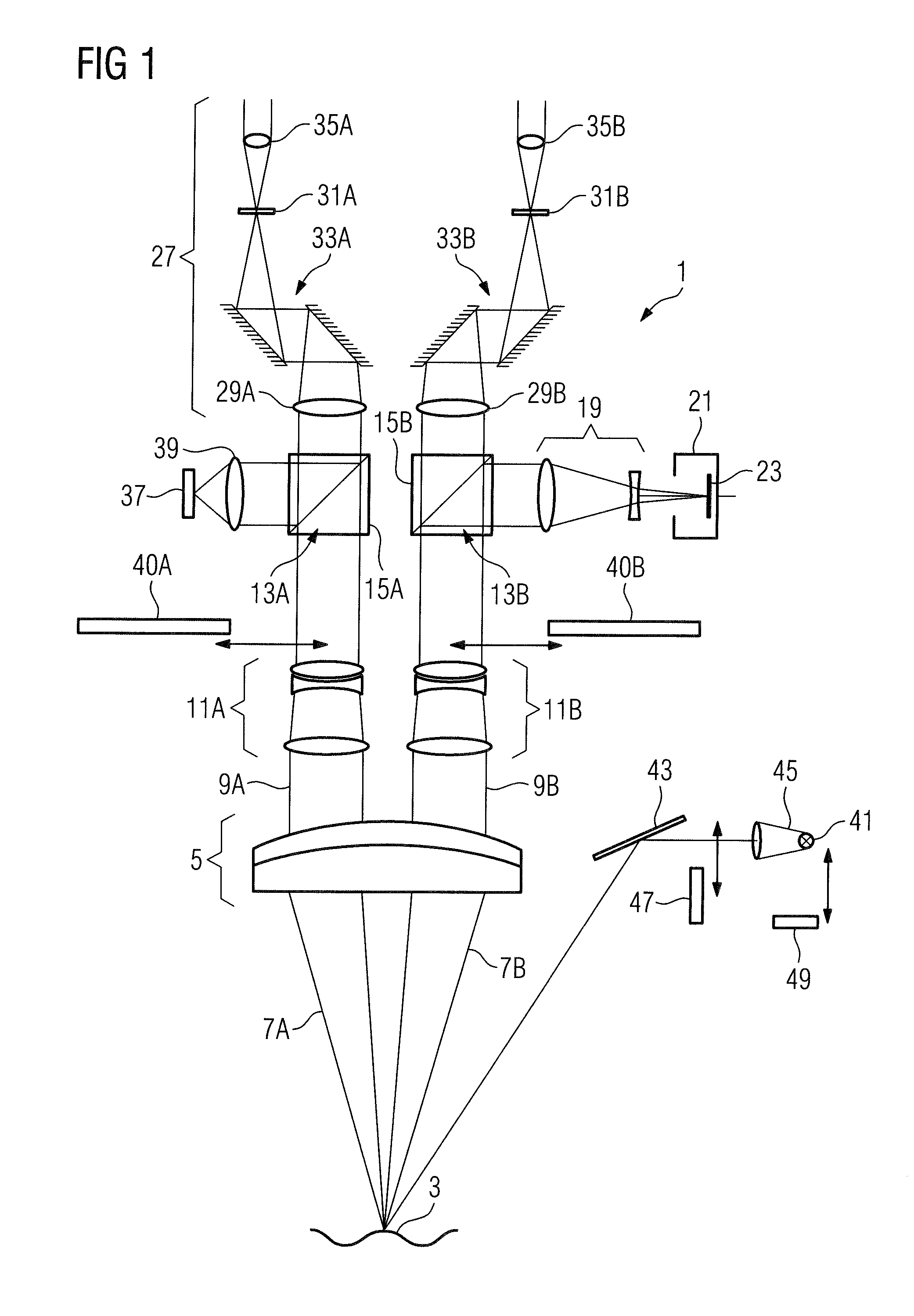
[0028]The stereomicroscope according to the invention is described below on the basis of the example of a surgical microscope. In this case, FIG. 1 shows the basic construction of a surgical microscope such as can substantially be realized in particular in the main observer beam path of the stereomicroscope according to the invention.

[0029]The surgical microscope 1 shown in FIG. 1 includes as essential constituents an objective 5 intended to face an object field 3, which objective can be embodied in particular as an achromatic or apochromatic objective. In the present embodiment, the objective 5 consists of two partial lenses cemented to one another, which form an achromatic objective. The object field 3 is arranged in the focal plane of the objective 5, such that it is imaged toward infinity by the objective 5. In other words, a divergent beam 7 emerging from the object field 3 is converted into a parallel beam 9 as it passes through the objective 5.

[0030]A magnification changer (1...


PUM


Abstract

A stereomicroscope including a stereoscopic main observer beam path having a main observer zoom system, a stereoscopic co-observer beam path having a co-observer zoom system, and a main objective common to the main observer beam path and the co-observer beam path. The co-observer beam path is coupled out from the main observer beam path via a geometrical beam splitter arranged between the main objective and the main observer zoom system, wherein in the co-observer beam path the co-observer zoom system succeeds the geometrical beam splitter and is constructed from lenses having dimensions such that both a first and a second stereoscopic partial beam of the co-observer beam path in each case pass through the lenses.

Description

CROSS REFERENCE TO RELATED APPLICATION[0001]This application claims priority of German patent application no. 10 2014 108 811.5, filed Jun. 24, 2014, the entire content of which is incorporated herein by reference.FIELD OF THE INVENTION[0002]The present invention relates to a stereomicroscope and more particularly a surgical microscope including a stereoscopic main observer beam path, a stereoscopic co-observer beam path and a main objective common to the main observer beam path and the co-observer beam path.BACKGROUND OF THE INVENTION[0003]JP 2005-070809 A discloses a stereomicroscope having a main observer beam path and a plurality of co-observer beam paths. In the stereomicroscope there exist a co-observer beam path which is coupled out from the main observer beam path in front of the main objective, that is, between main objective and observation object, and co-observer beam paths which are coupled out behind the main objective. The latter share with the main observer beam path ...

Claims


Application Information

Patent Timeline
Patent Type & Authority Applications(United States)
IPC IPC(8): G02B21/22G02B21/04G02B21/00G02B21/02
CPCG02B21/22G02B21/0012G02B21/04G02B21/025G02B21/18
Inventor HOEGELE, ARTURMUELLER, ANDREKOLSTER, DANIEL
Owner CARL ZEISS MEDITEC AG
Why Eureka
Try Eureka