Time multiplexed touch detection and power charging

a technology of power charging and touch detection, applied in the field of touch sensitive devices, can solve the problems of affecting the performance the introduction or addition of noise of the charger during the charging process, and the adverse effect of the touch sensor panel device, so as to prevent the adverse effect of the touch sensor panel, the introduction or addition of noise, and the adverse effect of one or more components

Active Publication Date: 2015-12-24
APPLE INC
View PDF23 Cites 20 Cited by
  • Summary
  • Abstract
  • Description
  • Claims
  • Application Information

AI Technical Summary

Benefits of technology

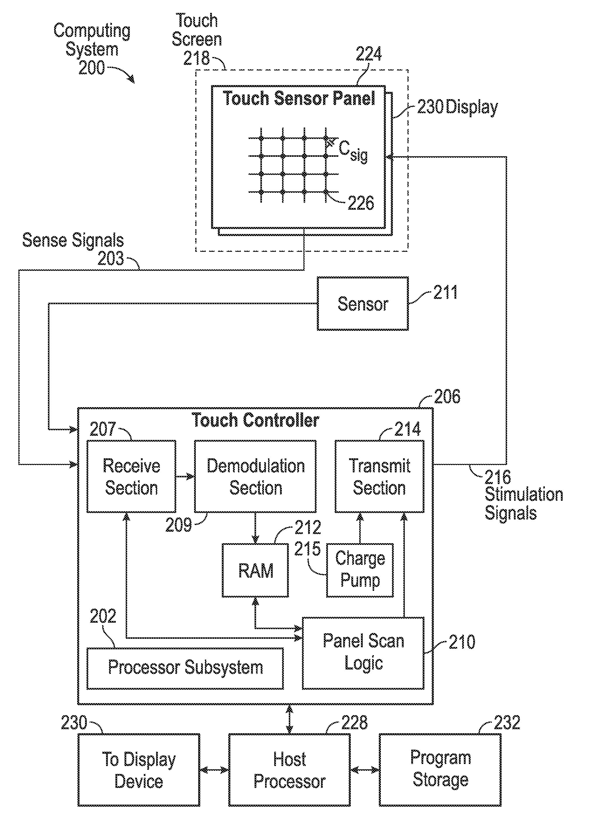
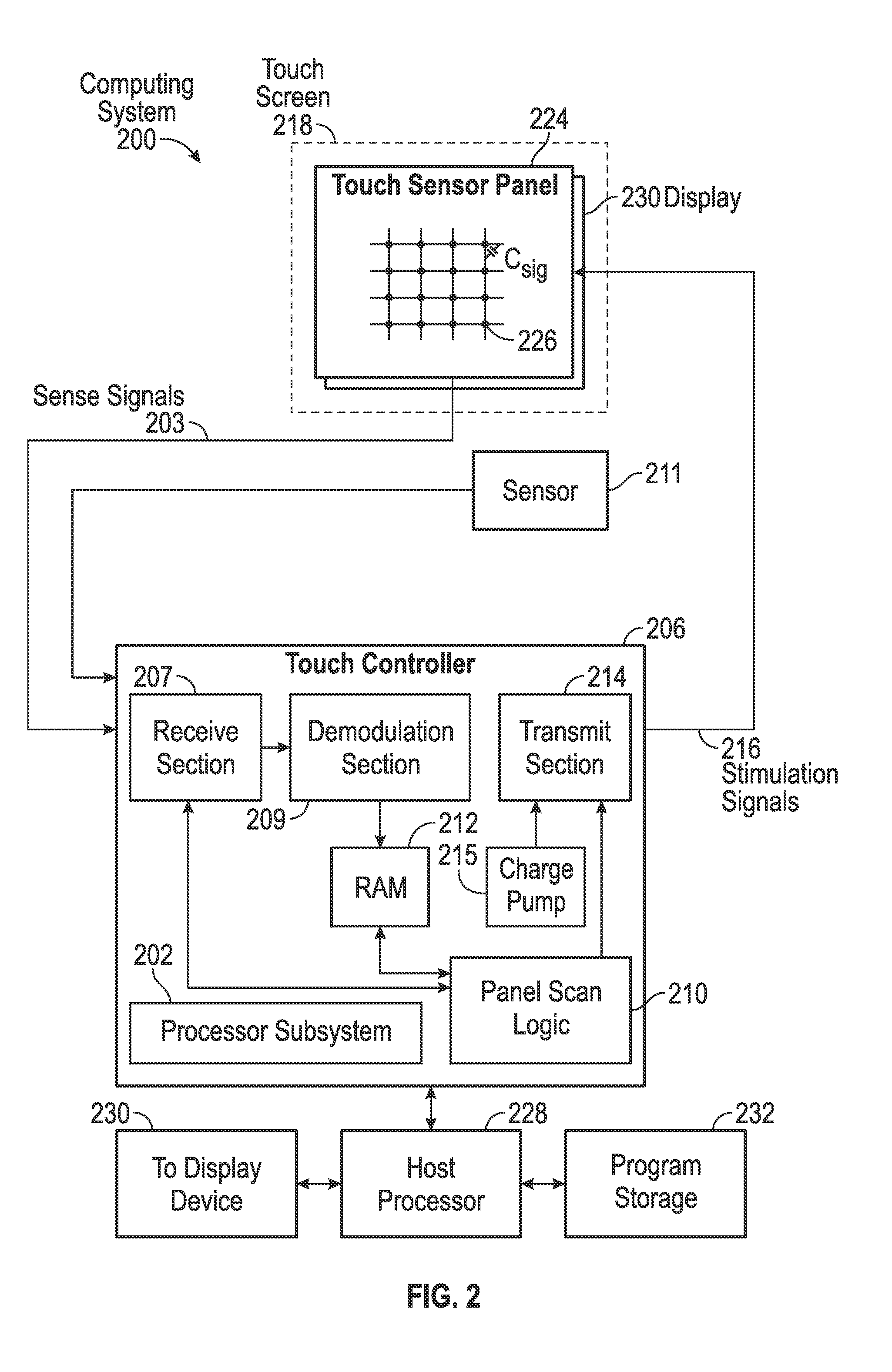
[0004]This relates to time multiplexed touch detection and power charging of touch sensitive devices. A power adapter or an inductive charger can charge a battery of a device, but can also introduce or add noise during the process of charging the battery. Touch pixels of a touch sensitive device can be stimulated by noise from the charger, and can adversely affect one or more components, such as the touch sensor panel. To prevent adverse effects to the touch sensor panel, while the device is charging, the touch controller can time multiplex touch scan periods and inductive charging periods and can discard touch scans or touch images affected by the noise.

Problems solved by technology

One limitation of touch sensor panel technologies is that noise can adversely affect the performance of a touch sensor panel device.
The charger can introduce noise while charging, which can prevent a touch sensor panel from distinguishing between a touch event (e.g., a user's contact of a touch sensor panel) and noise influencing the sensors of the touch sensor panel.
A power adapter or an inductive charger can charge a battery of a device, but can also introduce or add noise during the process of charging the battery.
Touch pixels of a touch sensitive device can be stimulated by noise from the charger, and can adversely affect one or more components, such as the touch sensor panel.

Method used


Image

  • Time multiplexed touch detection and power charging
  • Time multiplexed touch detection and power charging
  • Time multiplexed touch detection and power charging

Examples


Embodiment Construction

[0021]In the following description of examples, reference is made to the accompanying drawings which form a part hereof, and in which it is shown by way of illustration specific examples that can be practiced. It is to be understood that other examples can be used and structural changes can be made without departing from the scope of the disclosed examples.

[0022]Various techniques and process flow steps will be described in detail with reference to examples as illustrated in the accompanying drawings. In the following description, numerous specific details are set forth in order to provide a thorough understanding of one or more aspects and / or features described or referenced herein. It will be apparent, however, to one skilled in the art, that one or more aspects and / or features described or referenced herein may be practiced without some or all of these specific details. In other instances, well-known process steps and / or structures have not been described in detail in order to no...


PUM


Abstract

A method of scanning a touch sensor panel while the touch sensor panel is coupled to a power adapter is disclosed. The power adapter can charge a battery of a device, but can also introduce or add noise during the process of charging the battery. To prevent adverse effects to the touch sensor panel, while the device is charging, the touch controller can time multiplex touch scan periods and inductive charging periods and can discard touch scans or touch images affected by the noise. Determining whether a touch scan is a bad touch scan can include performing a touch scan across the array of touch pixels and making a determination based on the scan profile. In some examples, the profile can be quantified using different metrics such as the shape, instantaneous slope of tail ends, a full-width half-maximum, and a monotonicity of the curve of the scan profile.

Description

FIELD OF THE DISCLOSURE[0001]This relates generally to touch sensitive devices, and in particular, to a touch scan mode during device charging.BACKGROUND OF THE DISCLOSURE[0002]Many types of input devices are presently available for performing operations in a computing system, such as buttons or keys, mice, trackballs, touch sensor panels, joysticks, touch screens and the like. Touch screens, in particular, are becoming increasingly popular because of their ease and versatility of operation as well as their declining price. Touch screens can include a touch sensor panel, which can be a clear panel with a touch-sensitive surface. The touch sensor panel can be positioned in front of a display screen so that the touch-sensitive surface covers the viewable area of the display screen. Touch screens can allow a user to make selections and move a cursor by simply touching the display screen via a finger or stylus. In general, the touch screen can recognize a touch and position of the touch...

Claims


Application Information

Patent Timeline
Patent Type & Authority Applications(United States)
IPC IPC(8): G06F3/041H02J7/00
CPCH02J7/007G06F3/0418G06F3/04166G06F3/0446H02J7/00711
Inventor SAUER, CHRISTIAN M.MOYER, TODD K.PARNELL, ROBERT S.
Owner APPLE INC
Why Eureka
Try Eureka