Testing optimized binary modules

a binary module and optimization technology, applied in the field of binary module optimization technique, can solve the problems of the cost of testing required to verify whether or not the optimized binary modules are operating properly

Inactive Publication Date: 2015-12-24
IBM CORP
View PDF18 Cites 8 Cited by
  • Summary
  • Abstract
  • Description
  • Claims
  • Application Information

AI Technical Summary

Benefits of technology

[0020]These costs could be reduced if binary optimization and the testing of optimized binary modules were performed automatically in the background and without need for human intervention in the system environment (that is, production environment) in which the optimized binary program is executed.
[0095]The present disclosure is also able to realize a binary optimization system in which a series of operations can be performed transparently in the production environment without requiring manual construction of a testing environment or manual execution of test cases. This series of operations includes optimizing the regions in the original binary module in which branch coverage is expected to be achieved, testing the resulting optimized binary modules, and switching to the optimized binary modules.

Problems solved by technology

However, these users are concerned about the costs of testing required to verify whether or not the optimized binary modules are operating properly.

Method used


Image

  • Testing optimized binary modules
  • Testing optimized binary modules
  • Testing optimized binary modules

Examples


Embodiment Construction

[0112]The following is an explanation of an embodiment of the present disclosure with reference to the drawings. In the drawings described below, the same reference signs are used to denote the same elements unless otherwise noted. It should be understood that the embodiment of the present disclosure is used to explain a preferred embodiment of the present disclosure and that there is no intention to limit the scope of the present disclosure to the embodiment shown herein.

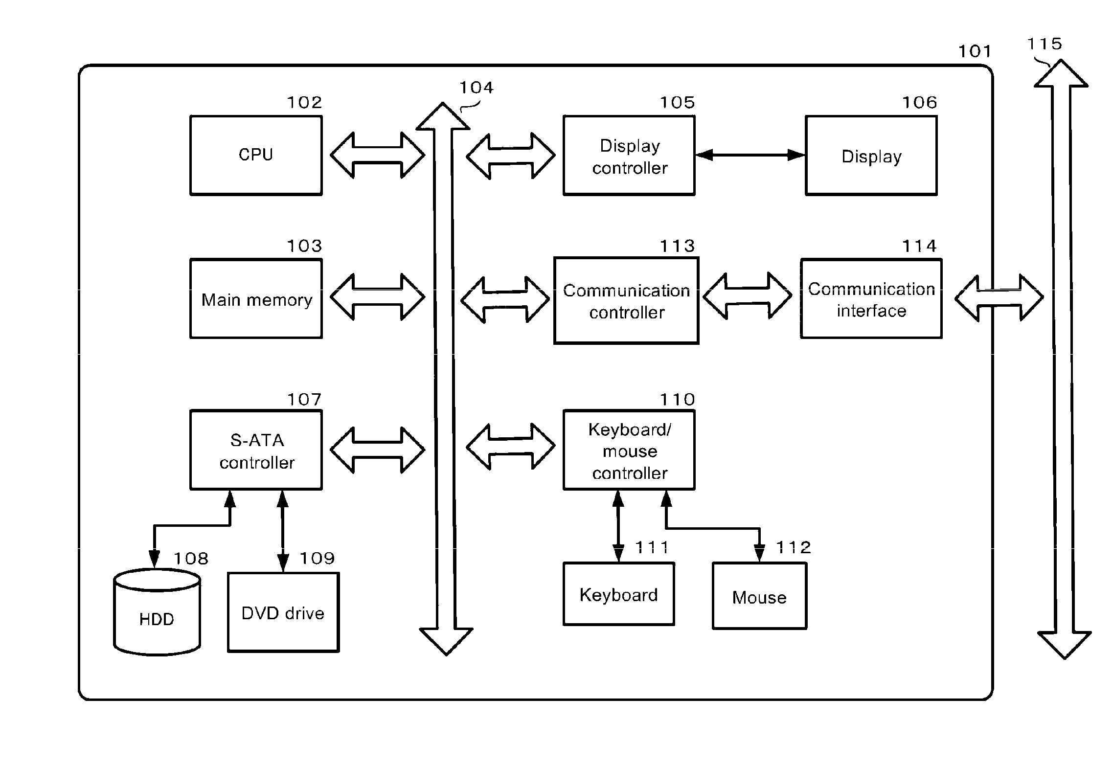
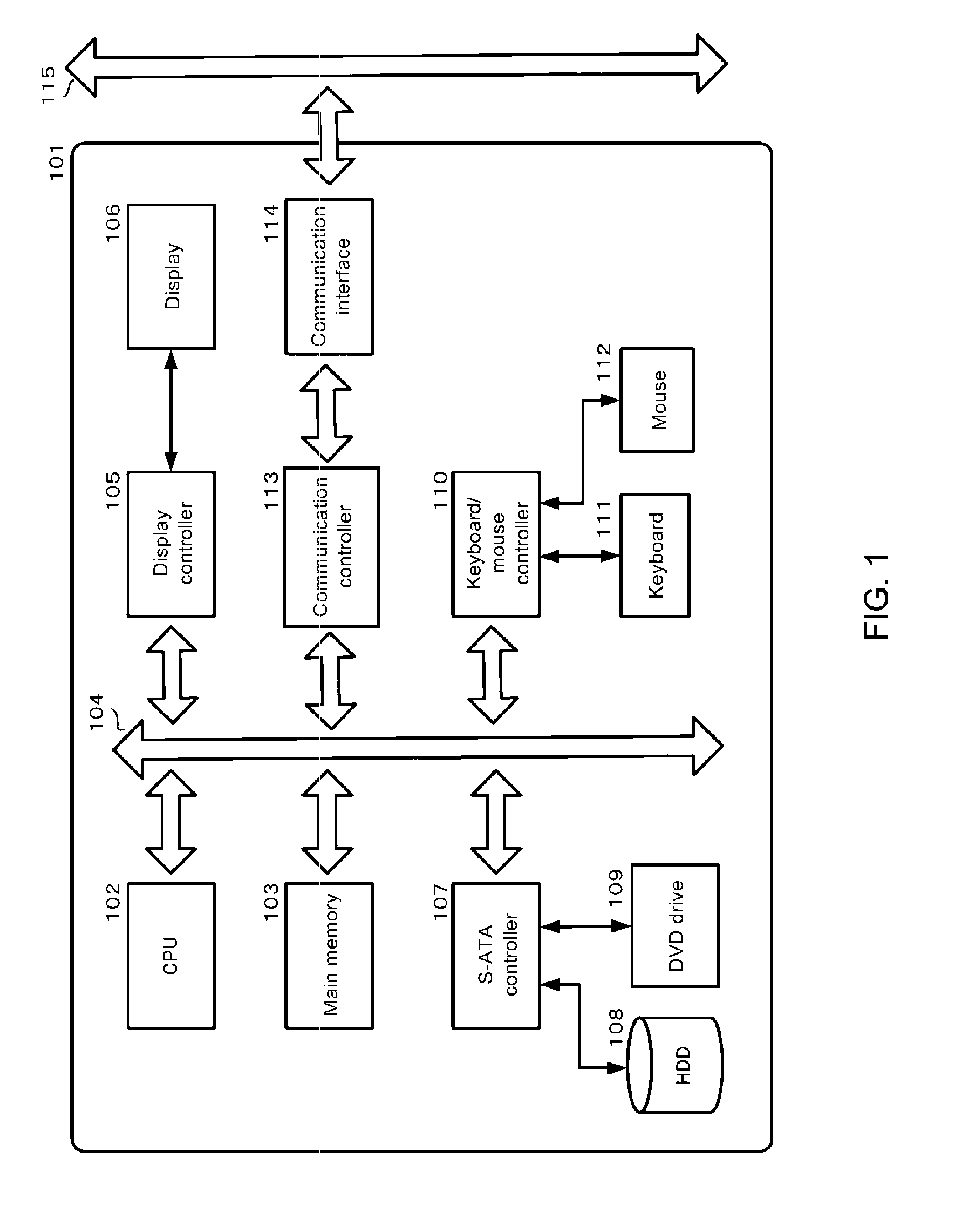
[0113]There are no particular restrictions on the computer that can be used in an embodiment of the present disclosure as long as the computer can be used to test an optimized binary module. Examples include main frame computers, server computers, desktop computers, notebook computers, all-in-one personal computers, tablets, and smartphones running on the Windows (registered trademark), Android (registered trademark) or iOS (registered trademark) operating systems.

[0114]FIG. 1 is a diagram showing an example of a c...


PUM


Abstract

Various embodiments test an optimized binary module. In one embodiment, a region in a set of original binary code of an original binary module in which branch coverage is expected to be achieved is selected based on a set of profile information. The region is selected as a target region to be optimized. An optimized binary module is created, where the target region has been optimized in the optimized binary module. The optimized binary module is verified by synchronizing execution of the optimized binary module with execution of the original binary module at a checkpoint while executing both the optimized binary module and the original binary module. The optimized binary module is further verified by comparing an output from executing the optimized binary module to an output from executing the original binary module.

Description

CROSS-REFERENCE TO RELATED APPLICATION[0001]This application is based upon and claims priority from U.S. patent application Ser. No. 14 / 621,890 filed on Feb. 13, 2015, which is based upon and claims priority from prior Japanese patent application number 2014-026911, filed on Feb. 14, 2014, the entire contents of both disclosures are hereby incorporated by reference herein.BACKGROUND[0002]The present disclosure generally relates to a binary module optimizing technique, and more particularly relates to a technique for testing an optimized binary module.[0003]In recent years, binary module optimizing technologies have garnered attention along with the updating and downsizing of hardware. Binary module optimizing technologies are the technologies used to optimize compiled binary modules that are legacy assets (for example, binary modules in COBOL programs) to create binary modules for new machines without having to recompile the source code.[0004]International Business Machines Corporat...

Claims


Application Information

Patent Timeline
Patent Type & Authority Applications(United States)
IPC IPC(8): G06F11/36
CPCG06F11/3692G06F8/443G06F8/52G06F11/3688G06F11/302G06F11/3409G06F11/3466G06F2201/865
Inventor KOJU, TOSHIHIKONAKAIKE, TAKUYA
Owner IBM CORP
Why Eureka
Try Eureka