
Voltage converting controller, voltage converting circuit, and control method for voltage converting

a voltage conversion circuit and voltage conversion technology, applied in the direction of power conversion systems, dc-dc conversion, instruments, etc., can solve the problems of severe undershoot, increasing electrical endurance of systems, and increasing integration level of electronic application apparatuses, so as to achieve desirable power conversion efficiency and improve the quality of output voltage.

Active Publication Date: 2015-12-24
RICHTEK TECH
View PDF4 Cites 2 Cited by
  • Summary
  • Abstract
  • Description
  • Claims
  • Application Information

AI Technical Summary

Benefits of technology

The patent describes a voltage converting controller, circuit, and control method that can reduce overshoot and undershoot of output voltage, and improve the quality of output voltage when a heavy load and light load change frequently. This is achieved by setting the operation frequency and voltage level based on the load current, which results in desirable power conversion efficiency.

Problems solved by technology

This is because at present an electronic application apparatus has an increasingly high integration level and increasingly complex functions; however, on the other hand, a requirement for electrical endurance of a system becomes increasingly high.
Therefore, the output voltage possibly causes a severe undershoot, and even causes abnormal work of a circuit.
However, in '472, when a heavy load and a light load frequently appear alternately, the frequency of the operation frequency is maintained above the minimum transient frequency, resulting in a sacrifice of power conversion efficiency.

Method used


Image

  • Voltage converting controller, voltage converting circuit, and control method for voltage converting
  • Voltage converting controller, voltage converting circuit, and control method for voltage converting
  • Voltage converting controller, voltage converting circuit, and control method for voltage converting

Examples


Embodiment Construction

[0037]In this disclosure, the term “couple” herein includes any direct and indirect electrical connection means. Therefore, if it is described herein that a first apparatus is coupled to a second apparatus, it represents that the first apparatus may be electrically connected to the second apparatus directly, or electrically connected to the second apparatus indirectly by using another apparatus or connection means.

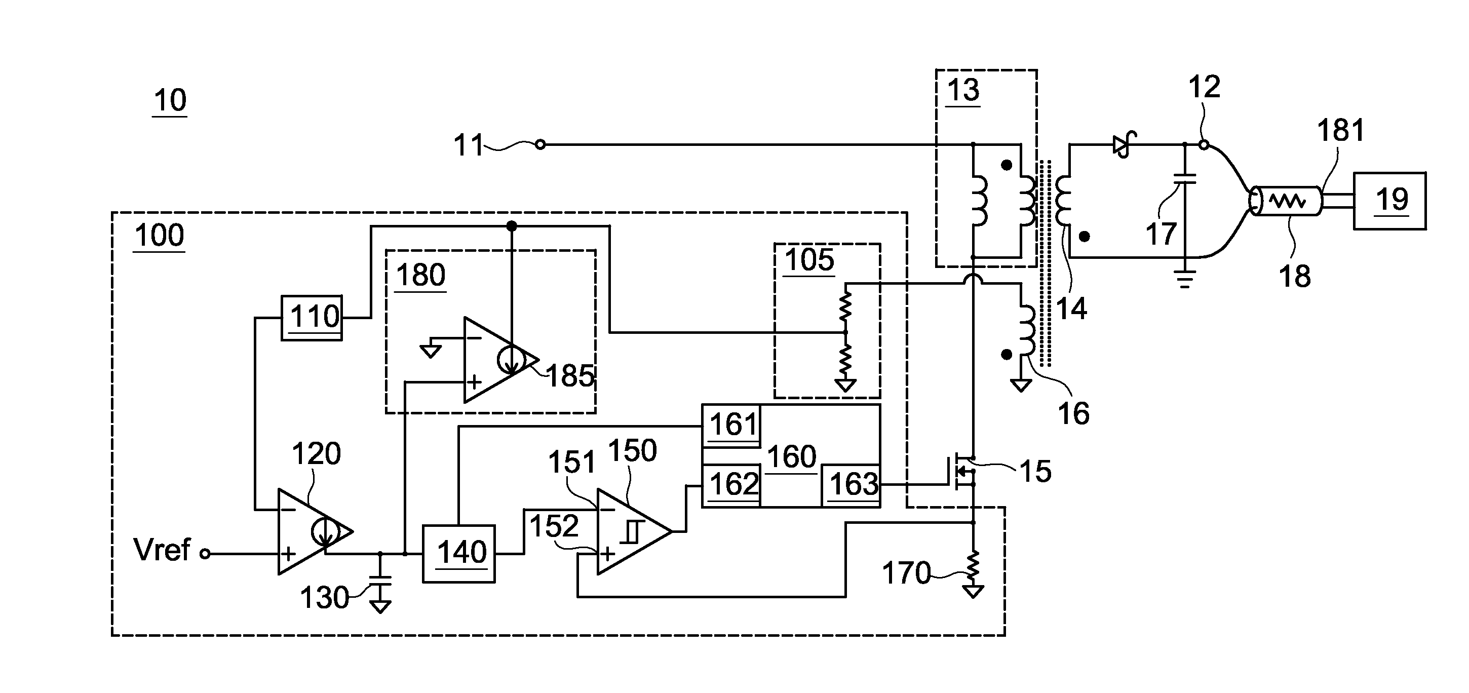
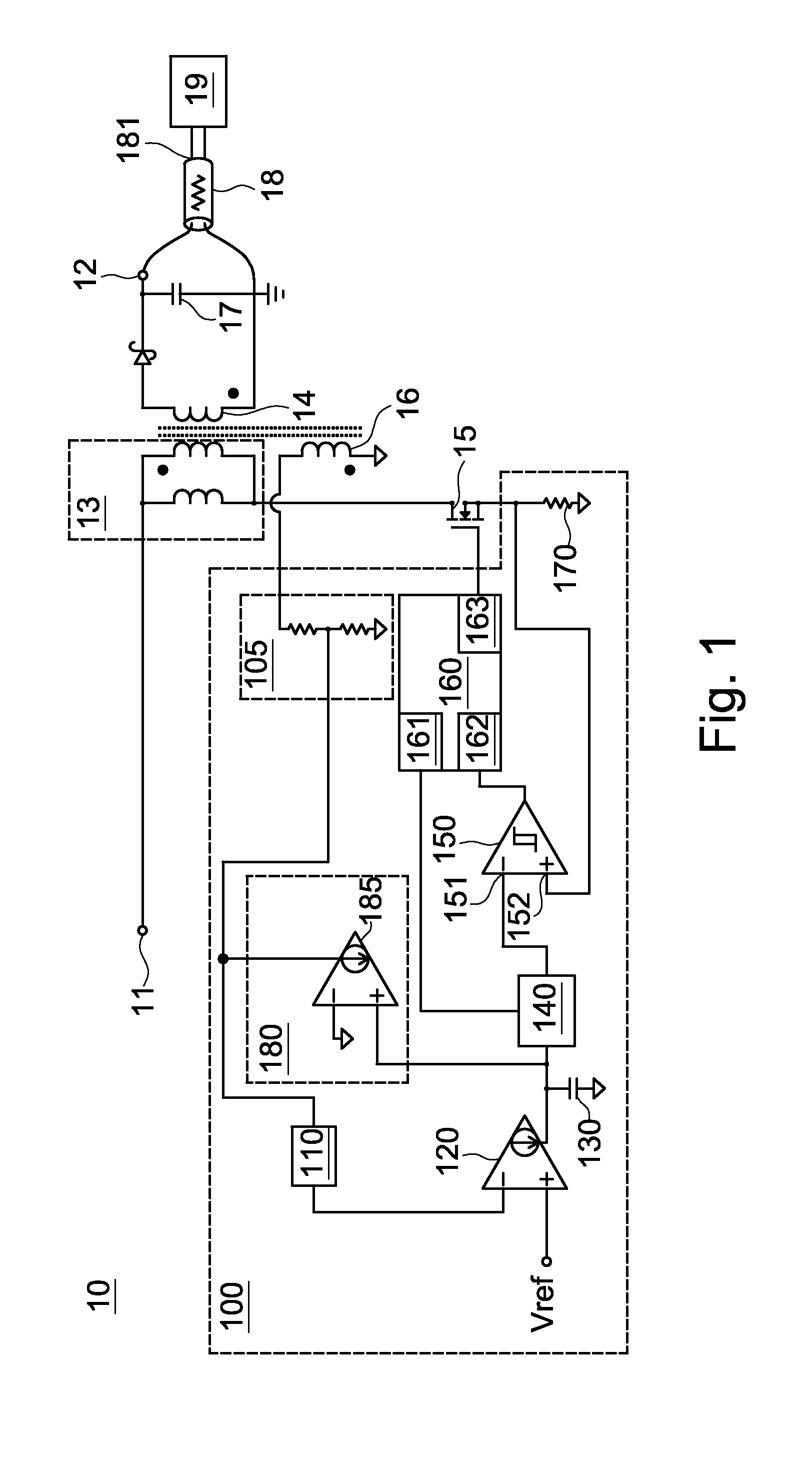
[0038]FIG. 1 is a circuit diagram of a voltage converting controller 100 and a switching voltage converting circuit 10 to which the voltage converting controller 100 is applied, which are disclosed by this disclosure.

[0039]The switching voltage converting circuit 10 converts an input voltage into a regulated secondary-side output voltage. The switching voltage converting circuit 10 further includes a primary coil 13, a secondary coil 14, and a switch 15.

[0040]The primary coil 13 is coupled to an input terminal 11 and receives the input voltage. The secondary coil 14 is cou...


PUM


Abstract

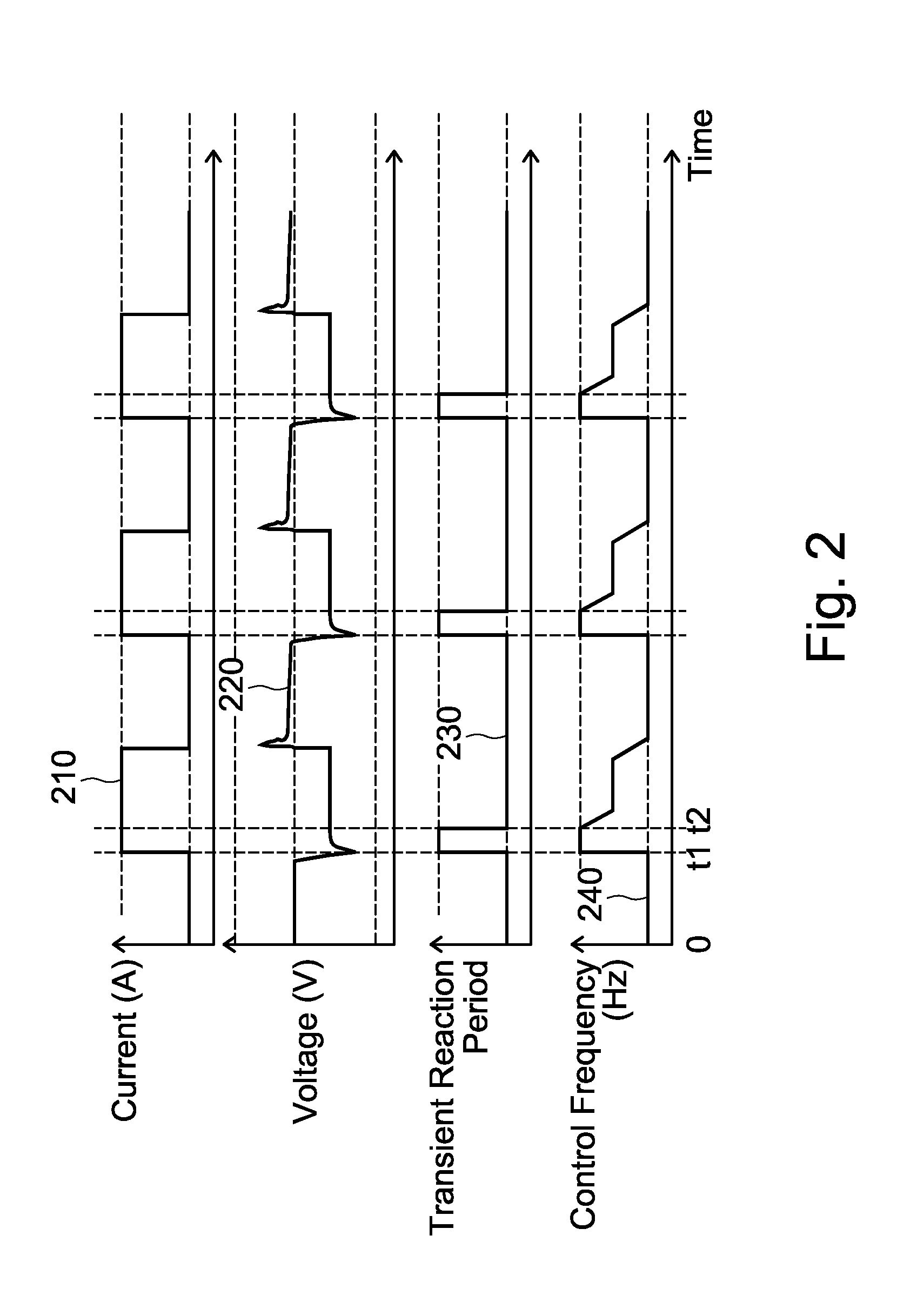
A voltage converting controller. When output current increases from a first current value to a second current value, the voltage converting controller temporarily sets a control frequency to a maximum frequency value. After a period of time, the voltage converting controller sets the control frequency to a target control frequency corresponding to the second current value. And, when the output current increases from the first current value to the second current value, the voltage converting controller temporarily sets a secondary-side output voltage to an transient output value; and after a period of time, the voltage converting controller sets a steady state value of the secondary-side output voltage to an output voltage steady state value corresponding to the second current value.

Description

CROSS-REFERENCE TO RELATED APPLICATIONS[0001]This non-provisional application claims priority claim under 35 U.S.C. §119(a) on Taiwan Patent Application No. 103121175 filed Jun. 19, 2014, the entire contents of which are hereby incorporated by reference.BACKGROUND[0002]1. Technical Field[0003]This disclosure relates to a voltage converting controller, a voltage converting circuit, and a control method for voltage converting, and in particular, to a voltage converting controller, a voltage converting circuit, and a control method for voltage converting which can mitigate an overshoot and undershoot of an output voltage and may also have desirable power conversion efficiency when a heavy load and a light load frequently appear alternately.[0004]2. Related Art[0005]A switching voltage converting circuit is one of various voltage converting circuits, and in a manner of switching a power switch, regulates energy stored on an inductive component (for example, a transformer) to supply the ...

Claims


Application Information

Patent Timeline
Patent Type & Authority Applications(United States)
IPC IPC(8): H02M3/335
CPCH02M3/33507H02M3/33523H02M2001/0019H02M1/0019
Inventor LEE, CHUH CHINGTANG, CHIEN-FUHUANG, CHUN SHIH
Owner RICHTEK TECH
Learn More