Circuit and method for reducing overshoots in adaptively biased voltage regulators

a voltage regulator and adaptive bias technology, applied in the field of voltage regulator circuits, can solve the problems of large area demand for large currents, poor transient response of conventional linear regulators, and unsuitable circuit schemes for their desired applications, and achieve the effect of reducing overshoots

Active Publication Date: 2011-07-19
CYPRESS SEMICON CORP
View PDF6 Cites 22 Cited by
  • Summary
  • Abstract
  • Description
  • Claims
  • Application Information

AI Technical Summary

Benefits of technology

[0015]According to a second aspect of the present invention, a method to reduce overshoots in adaptively biased voltage regulators includes a step of adaptively biasing a plurality of transistors to form an adaptively biased current mirror circuit; and coupling at least one source degenerate resistor to the adaptively biased current mirror circuit to limit an output peak current of the voltage regulator circuit to maintain a predetermined start-up time of the voltage regulator circuit.

Problems solved by technology

Conventional linear regulators suffer from poor transient response.
Although adaptive biasing improves the start up time of ultra low power voltage regulators, a disadvantage of the conventional solution 200 is that intolerable overshoots are observed at the regulator output that make the given circuit scheme unsuitable for its desired applications.
Further disadvantages of conventional solutions include huge area demand for large currents, compensation at higher tail current during start up if not compensated at the load, and the need for a pulse generation for turning off the switched-in current after start-up if the regulator gets enabled with a signal (area impact).
If the digital signal is not available during start-up, then design-complexity will increase (e.g., comparators may be used to sense the voltage and turn-off).

Method used


Image

  • Circuit and method for reducing overshoots in adaptively biased voltage regulators
  • Circuit and method for reducing overshoots in adaptively biased voltage regulators
  • Circuit and method for reducing overshoots in adaptively biased voltage regulators

Examples


Embodiment Construction

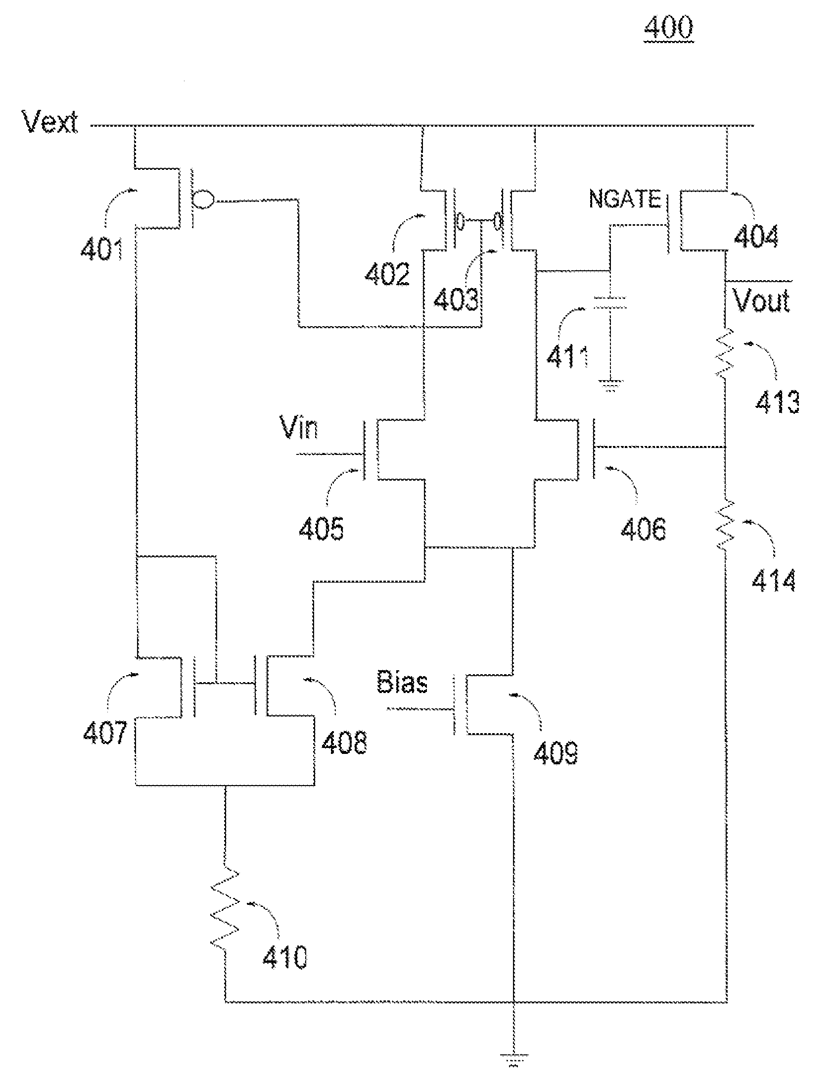
[0027]Exemplary embodiments of the present invention are directed to a circuit and method for reducing overshoots in adaptively biased voltage regulators. Source degeneration of the adaptive bias current mirrors is used as a self-corrective mechanism to limit the current when it builds very high. Thus, the overshoots at the output of the adaptively biased voltage regulator are minimized and the start up time specification of the voltage regulator is maintained. In accordance with an exemplary embodiment of the present invention, the voltage regulator circuit includes an adaptive bias current mirror circuit comprising a first transistor and a second transistor. The first transistor and the second transistor include source nodes coupled to a drain node of the first transistor. A common node is coupled to the source node of the first transistor and the source node of the second transistor. A source degenerate resistor is coupled to the adaptive bias current mirror circuit and is couple...


PUM


Abstract

Disclosed are a circuit and a method for adaptively biasing a voltage regulator with minimal output overshoot. The circuit includes an adaptive bias current mirror circuit further including a first transistor and a second transistor, the first transistor and the second transistor having source nodes coupled to a drain node of the first transistor. The circuit includes a common node coupled to the source node of the first transistor and the source node of the second transistor, wherein a source degenerate resistor is coupled to the adaptive bias current mirror circuit and is coupled to the common node and wherein the source degenerate resistor is configured to limit an output peak current of the voltage regulator circuit.

Description

[0001]This application claims priority under 35 U.S.C. §119(e) to U.S. Provisional Application No. 60 / 876,806, filed on Dec. 22, 2006, the entire contents of which are hereby incorporated by reference herein.BACKGROUND[0002]1. Field of the Invention[0003]The present invention relates to voltage regulator circuits. More particularly, the present invention relates to a circuit and method for reducing overshoots in adaptively biased voltage regulators.[0004]2. Background Information[0005]A conventional voltage regulator, which is sometimes referred to as a linear regulator, is used to provide power to low voltage digital and analog circuits, where point-of-load and line regulation is important. Conventional linear regulators suffer from poor transient response. Transient response is the behavior of the linear regulator after an abrupt change of either the load current (load response) or the input voltage (line response). A minimum undershoot and overshoot of the regulated voltage and a...

Claims


Application Information

Patent Timeline
Patent Type & Authority Patents(United States)
IPC IPC(8): G05F3/16
CPCG05F1/56G05F1/575
Inventor PRASAD, SOUNDARARAJAN SRINIVASAKRISHNA, DAMARAJU NAGA RADHA
Owner CYPRESS SEMICON CORP
Why Eureka
Try Eureka