Eureka AIR delivers breakthrough ideas for toughest innovation challenges, trusted by R&D personnel around the world.

Current switching circuit for high-speed current rudder digital-to-analog converter

A current-steering digital-to-analog converter technology, applied in the field of integrated circuits, can solve problems affecting the dynamic characteristics of the digital-to-analog converter, the influence of the dynamic characteristics of the digital-to-analog converter, and the poor symmetry of the differential switch signal, so as to achieve easy matching and weaken over Chong, improve the effect of symmetry

Inactive Publication Date: 2011-08-17
ZHEJIANG UNIV
View PDF4 Cites 24 Cited by
  • Summary
  • Abstract
  • Description
  • Claims
  • Application Information

AI Technical Summary

Problems solved by technology

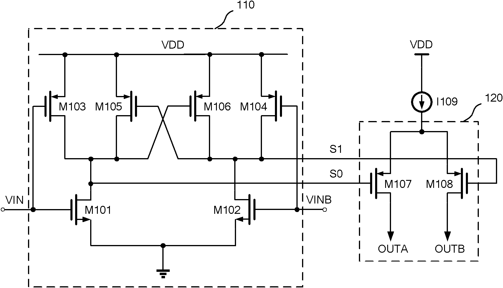
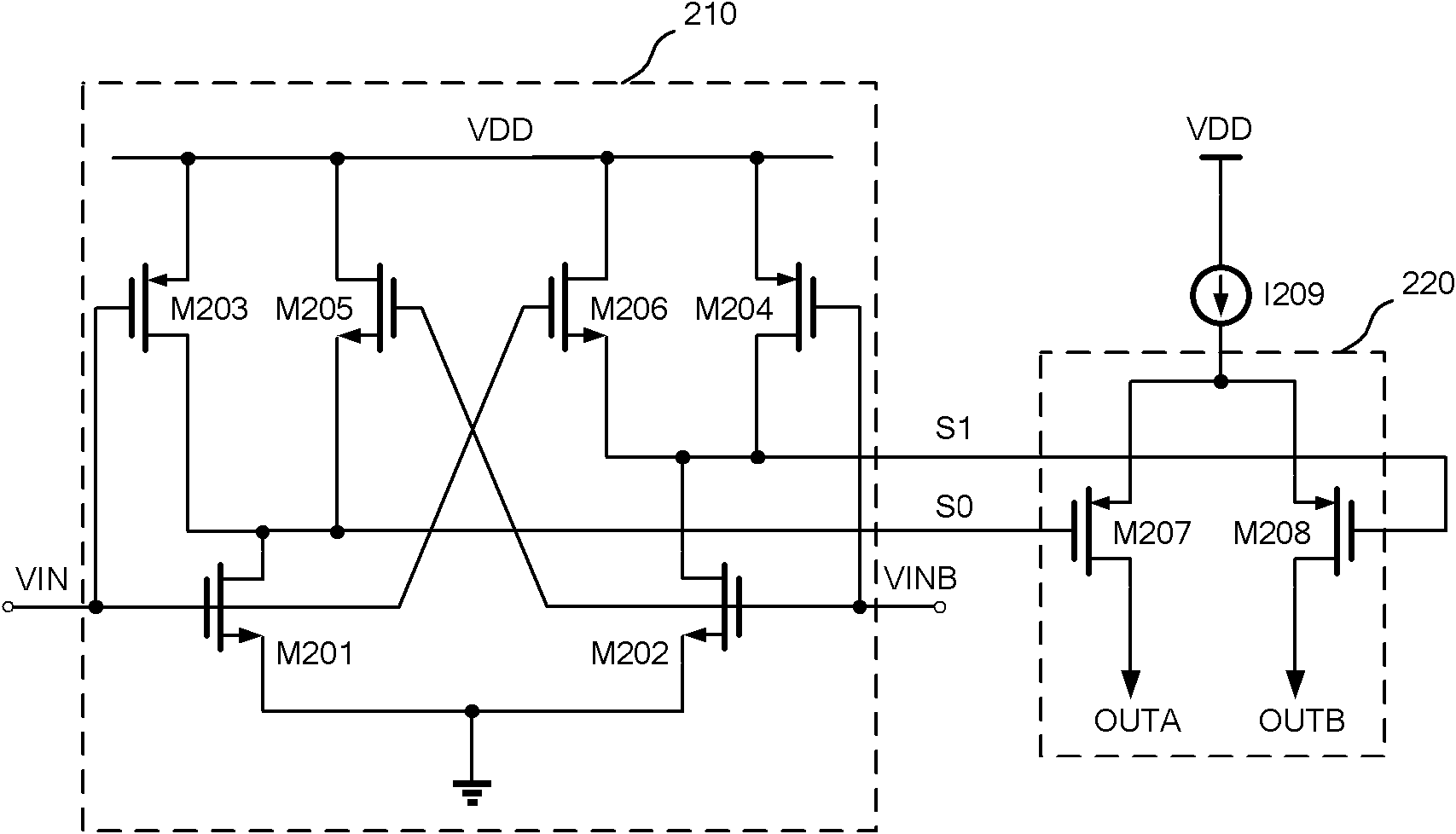
[0010] but figure 2 The disadvantage of the current switch circuit is that the symmetry of the rising and falling edges of the differential switching signals S0 and S1 is relatively poor, and the differential switching signal has a large overshoot phenomenon when it jumps from high level to low level
The asymmetry between the rising edge and the falling edge of the signal will cause inter-symbol interference (ISI), which will affect the dynamic characteristics of the digital-to-analog converter. At the same time, the differential switch signal jumps from high level to low level Usually, the overshoot will affect the output feedthrough through the lower-level current switch, and then affect the dynamic characteristics of the high-speed current steering digital-to-analog converter, such as spurious-free dynamic range (SFDR)

Method used


Image

  • Current switching circuit for high-speed current rudder digital-to-analog converter
  • Current switching circuit for high-speed current rudder digital-to-analog converter
  • Current switching circuit for high-speed current rudder digital-to-analog converter

Examples


Embodiment Construction

[0035] In order to describe the present invention more specifically, the technical solutions and related principles of the present invention will be described in detail below in conjunction with the accompanying drawings and specific embodiments.

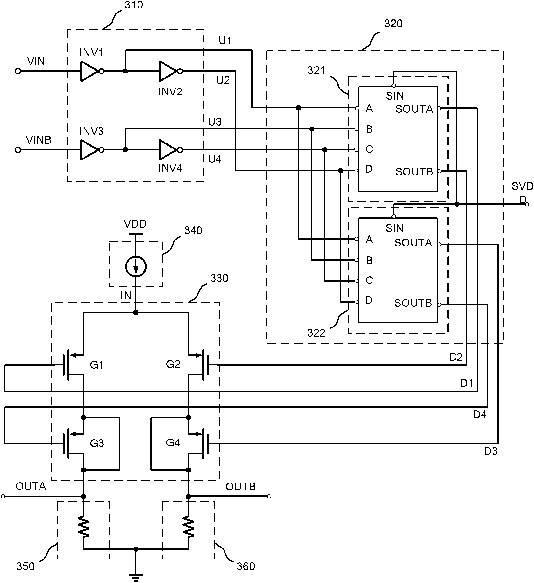
[0036] Such as image 3 As shown, a current switch circuit for a high-speed current steering digital-to-analog converter includes a switch main circuit 330, a constant current circuit 340 that provides a constant current source for the switch main circuit 330, and a circuit that provides a differential switch signal for the switch main circuit 330. The switch driving circuit 320 and the four-phase control signal generating circuit 310 providing differential control signals for the switch driving circuit 320 .

[0037] Such as image 3 and Figure 4 As shown, the four-phase control signal generating circuit 310 includes four inverters, wherein the input terminal of the first inverter INV1 serves as the first input terminal of the f...


PUM


Abstract

The invention discloses a current switching circuit for a high-speed current rudder digital-to-analog converter, comprising a switch main body circuit, a constant-current circuit which provides a constant flow source for the switch main body switch, a switch drive circuit which provides difference switching signals to the switch main body circuit and a four-phase control signal generating circuit which provides difference control signals for the switch drive circuit. A pre-breakover pull-down MOS (Metal Oxide Semiconductor) tube is adopted in the switch drive circuit , and a clock feedthrough compensation structure is applied to the switch main body circuit, thus overshooting of the difference switching signals is greatly weakened, falling edges of the difference switching signals at the initial stage of hopping become gentle, symmetry of rising and falling edges of the difference switching signals in case of low swing amplitude is improved and clock feedthrough errors resulting from the difference switching signals are effectively reduced. The current switching circuit is especially applicable to the high-speed and high-precision digital-to-analog converter.

Description

technical field [0001] The invention belongs to the technical field of integrated circuits, and in particular relates to a current switch circuit for a high-speed current steering digital-to-analog converter. Background technique [0002] Human needs for more convenient and effective communication methods have promoted the continuous development of information technology, such as modern wireless broadband communication technology, multimedia image processing and digital technology. With the introduction of the system on chip (system on chip, SOC) concept, it is required to integrate all analog signals and digital signals in the same system. High-performance data converter interfaces, including digital-to-analog converters (digital to analog, DAC) and analog-to-digital converters (analog to digital, ADC) have gradually become one of the most challenging modules in these technical research fields. With the increasing demand for bandwidth and information processing capability,...

Claims


Application Information

Patent Timeline
Patent Type & Authority Applications(China)
IPC IPC(8): H03K17/567
Inventor 薛晓博何乐年刘国家
Owner ZHEJIANG UNIV
Why Eureka
Eureka Blog
Learn More