Buck converter based on variable conduction time control

An on-time, converter technology, applied in control/regulation systems, output power conversion devices, conversion of DC power input to DC power output, etc. effect of speed

Active Publication Date: 2019-06-21
UNIV OF ELECTRONICS SCI & TECH OF CHINA
View PDF5 Cites 22 Cited by
  • Summary
  • Abstract
  • Description
  • Claims
  • Application Information

AI Technical Summary

Problems solved by technology

[0003] However, the traditional constant on-time control mode has the following problems: such as figure 1 Shown, T ON Generate the threshold voltage V of the negative input terminal of the second comparator Comp2 in the module TH fixed, the charging capacitor C TH The charging current I C fixed, so the on-time T ON is fixed, but the minimum off-time T is generally designed in the actual circuit OFFMIN
Therefore, at the load current or the reference voltage V REF When a step occurs, the conventional constant on-time control mode Buck converter produces a duty cycle that can only reach a maximum of T ON / (T ON +T OFFMIN ), limiting the further improvement of the response speed

Method used


Image

  • Buck converter based on variable conduction time control
  • Buck converter based on variable conduction time control
  • Buck converter based on variable conduction time control

Examples


Embodiment Construction

[0041] The present invention will be described in detail below in conjunction with the accompanying drawings and specific embodiments.

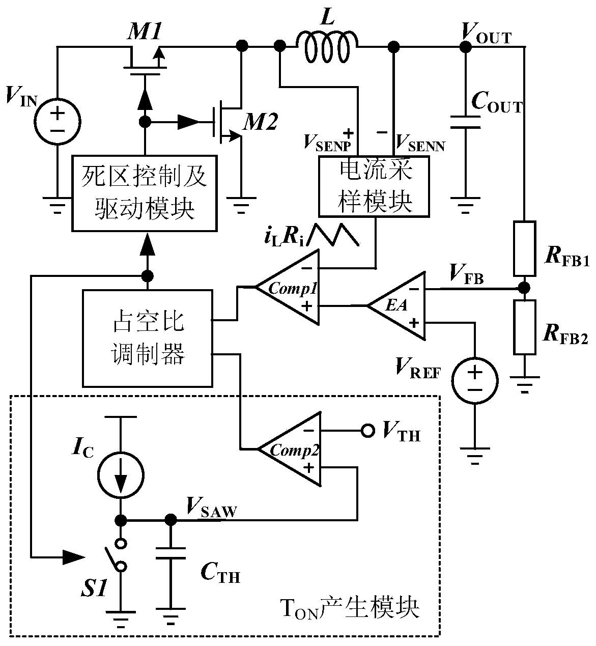
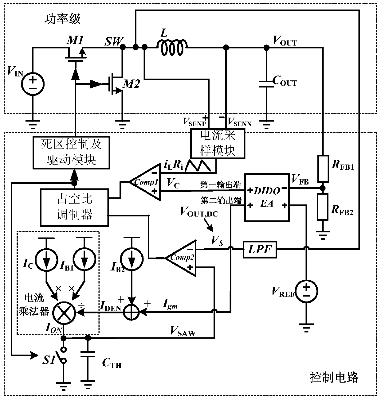
[0042] The overall structure of a Buck converter based on variable on-time control proposed by the present invention is as follows: figure 2 As shown, including the power stage and the control loop, the power stage includes the first switch tube M1, the second switch tube M2, the power inductor L and the output capacitor C OUT , the drain of the first switching tube M1 is connected to the input voltage V of the Buck converter IN , its source is used as the switching node SW of the Buck converter to connect the drain of the second switching tube M2 and one end of the power inductor L, the source of the second switching tube M2 is grounded; the other end of the power inductor L is the output of the Buck converter terminal and through the output capacitor C OUT back to ground.

[0043] The control loop consists of a first divider resistor R ...


PUM


Abstract

The invention relates to a Buck converter based on variable conduction time control, belonging to the technical field of analog integrated circuits. An error current signal and an error voltage signalis generated by using a double-input and double-output error amplifier, and the error voltage signal is compared with a sampled voltage signal containing inductance current information to serve as aninput signal of a duty ratio modulator; variable current generated by a current multiplier is used as charging current of a charging capacitor, and the conduction time of the Buck converter is variable; the voltage at the switching node of the Buck converter is filtered and then compared with the voltage of the charging capacitor to serve as another input signal of the duty ratio modulator, a logic signal with a controlled duty ratio is generated and serves as a gate driving signal of a power tube of the Buck converter after dead zone control and driving, response speed is effectively improved, and undershoot or overshoot of the output voltage VOUT is reduced.

Description

technical field [0001] The invention belongs to the technical field of analog integrated circuits, and in particular relates to a Buck converter based on variable conduction time control. Background technique [0002] The traditional constant on-time (COT, Constant On-Time) control is a pulse frequency modulation (PFM, Pulse Frequency Modulation) control technology, which makes the switching converter conduct for a fixed time in each switching cycle, by controlling the off The off time realizes the adjustment of the output voltage. Such as figure 1 Shown is a schematic diagram of the overall structure of the traditional Buck converter based on constant on-time control, T ON The generation module generates a fixed on-time T ON , the first comparator Comp1 modulates the off-time based on the minimum value of the valley current detection inductor current, thereby adjusting the switching cycle. Buck converters with constant on-time control have the advantages of high light l...

Claims


Application Information

Patent Timeline
Patent Type & Authority Applications(China)
IPC IPC(8): H02M3/158
Inventor 甄少伟曾鹏灏陈佳伟章玉飞黄龙罗萍张波
Owner UNIV OF ELECTRONICS SCI & TECH OF CHINA
Why Eureka
Try Eureka