

Image display device and head-mounted display
a display device and display device technology, applied in the field of image display devices and head-mounted displays, to achieve the effect of a more compact and compact structur
- Summary
- Abstract
- Description
- Claims
- Application Information
AI Technical Summary
Benefits of technology
Problems solved by technology
Method used
Image

Examples
first embodiment
[0037]Firstly, an image display device according to a first embodiment of the invention will be explained.
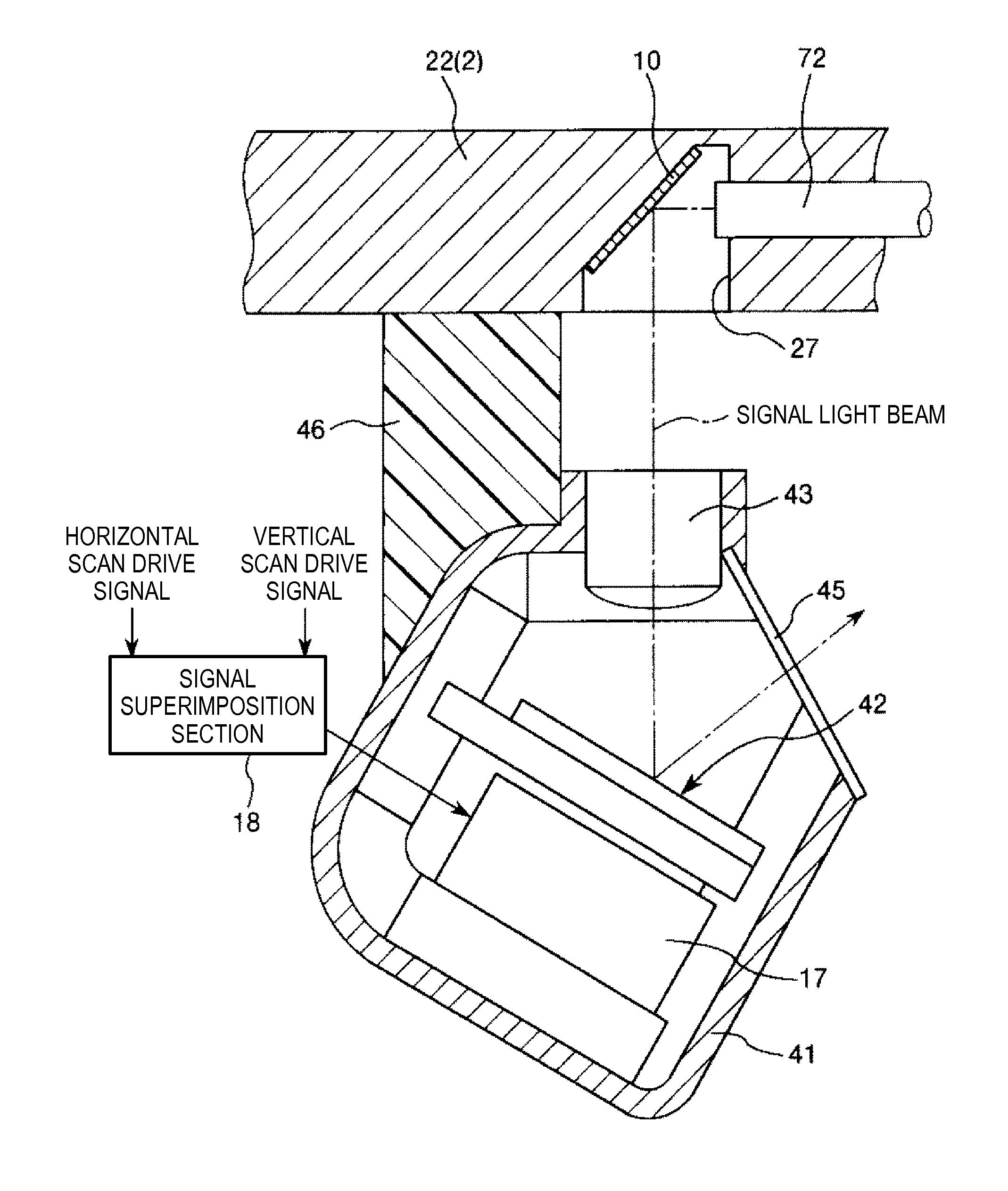
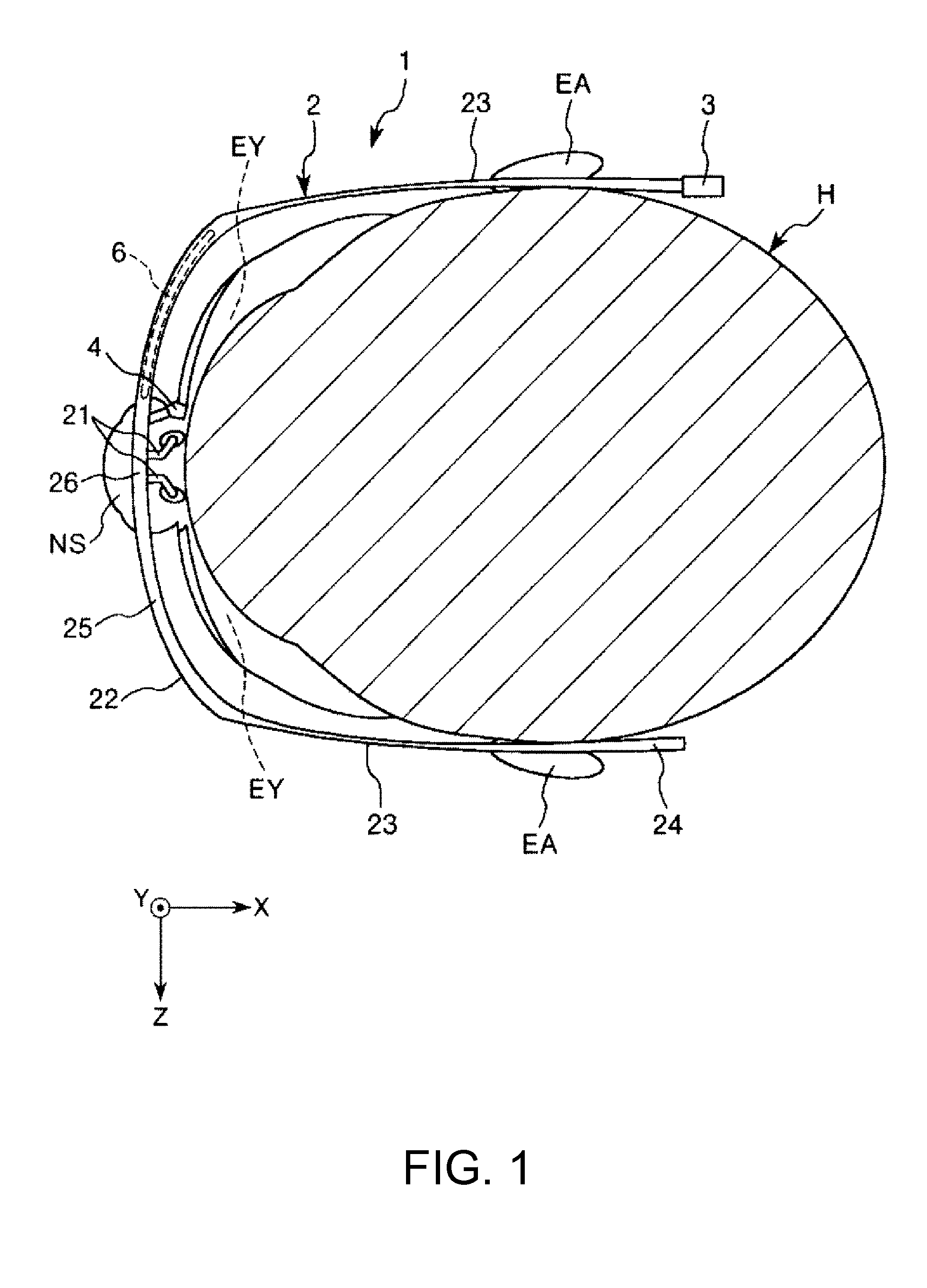
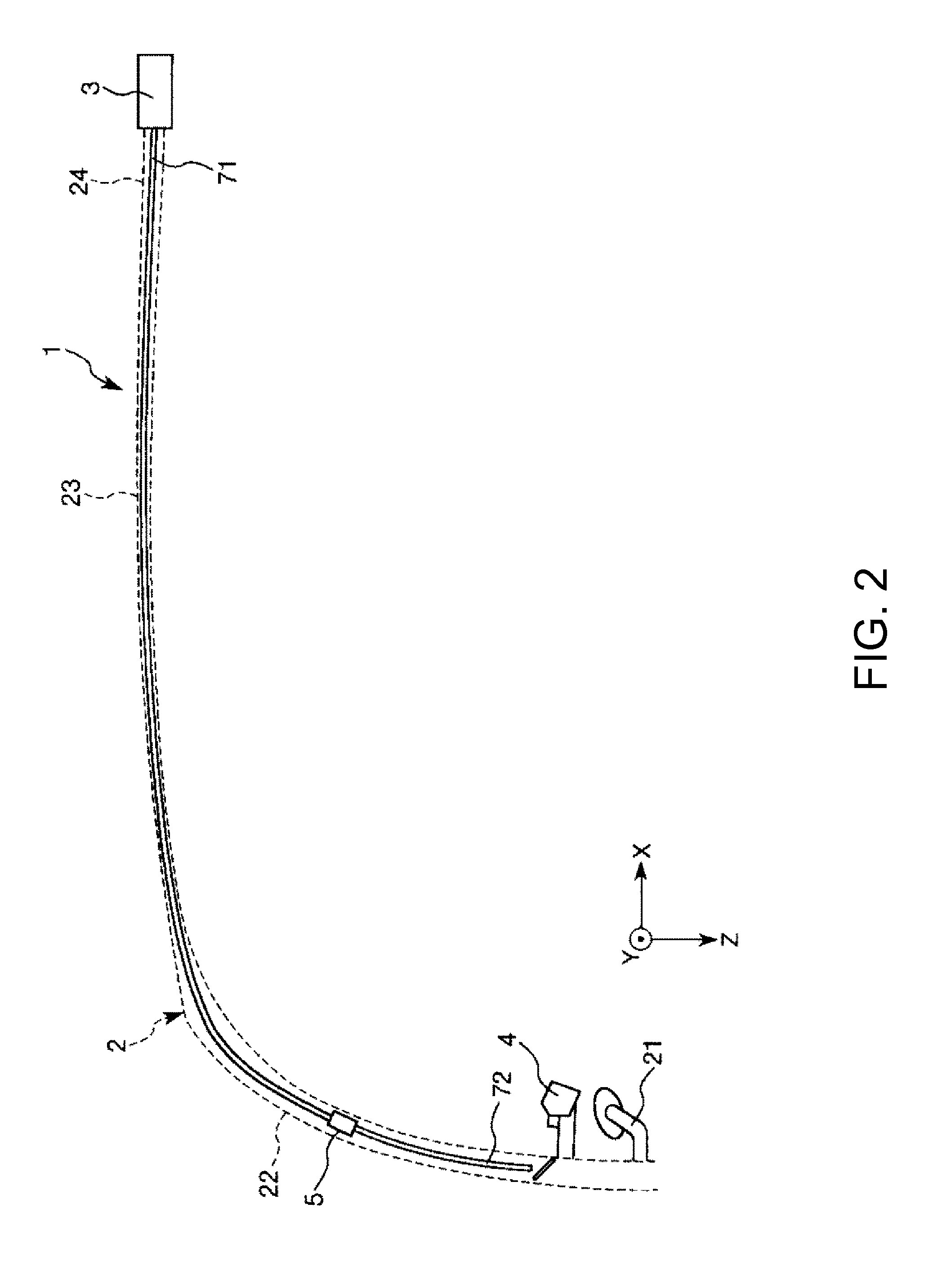
[0038]FIG. 1 is a diagram showing a schematic configuration of the image display device (a head-mounted display) according to the first embodiment of the invention, and FIG. 2 is a partial enlarged view of the image display device shown in FIG. 1. Further, FIG. 3 is a schematic configuration diagram of a signal generation section of the image display device shown in FIG. 1, FIG. 4 is a diagram showing a schematic configuration of a light scanning section included in a scan light emitting section shown in FIG. 1, and FIG. 5 is a diagram for explaining an action of the light scanning section shown in FIG. 4. FIG. 6 is a perspective view showing a schematic configuration of each of the switching sections shown in FIG. 3, FIG. 7 is a plan view of each of the switching sections shown in FIG. 6, and FIGS. 8A and 8B are diagrams for explaining an action of each of the switching section...
second embodiment
[0137]Then, an image display device according to a second embodiment of the invention will be explained.
[0138]FIG. 9 is a schematic configuration diagram of a signal generation section of the image display device according to the second embodiment of the invention.
[0139]Hereinafter, the second embodiment will be described. The following explanation is focused mainly on the differences from the first embodiment described above, and the explanation of substantially the same matters will be omitted. Further, in the drawings, the constituents substantially identical to those of the embodiment described above are denoted with the same reference symbols.
[0140]The signal generation section 3 related to the second embodiment is substantially the same as the signal generation section 3 related to the first embodiment except the point that the arrangement of the switching sections 30 is different.
[0141]Specifically, in the first embodiment, the switching sections 30R, 30G, and 30B are dispose...
third embodiment
[0145]Then, an image display device according to a third embodiment of the invention will be explained.
[0146]FIGS. 10A and 10B are diagrams for explaining an action of a switching section included in a signal generation section of the image display device according to the third embodiment of the invention. It should be noted that the signal light beam L1 shown in FIGS. 10A and 10B schematically shows the waveform of the signal light beam.
[0147]Hereinafter, the third embodiment will be described. The following explanation is focused mainly on the differences from the first embodiment described above and the explanation of substantially the same matters will be omitted. Further, in the drawings, the constituents substantially identical to those of the embodiments described above are denoted with the same reference symbols.
[0148]The signal generation section 3 related to the third embodiment is substantially the same as the signal generation section 3 related to the first embodiment ex...
PUM
| Property | Measurement | Unit |
|---|---|---|
| voltage | aaaaa | aaaaa |
| refractive index | aaaaa | aaaaa |
| color | aaaaa | aaaaa |
Abstract
Description
Claims
Application Information