
Anti-glare and light extinction optical lens

an optical lens and anti-glare technology, applied in the field of optical lenses, can solve the problems of damage to eyes, eye damage, and even permanent damage to the retina, so as to reduce and eliminate eye damage, increase the value of color, and increase the visual effect

Inactive Publication Date: 2018-08-09
HE SUNG GLASSES CO LTD
View PDF5 Cites 2 Cited by
  • Summary
  • Abstract
  • Description
  • Claims
  • Application Information

AI Technical Summary

Benefits of technology

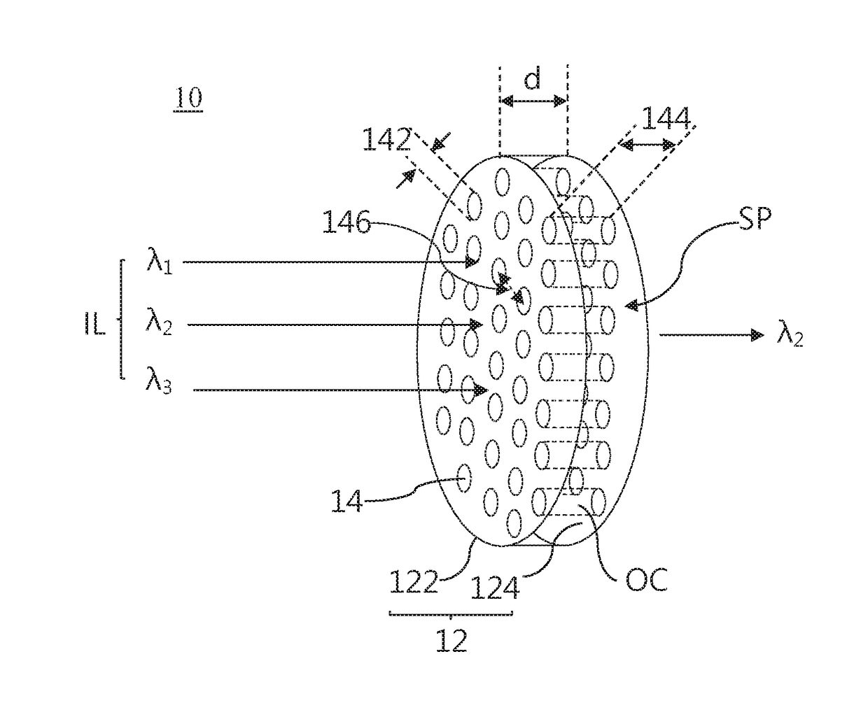
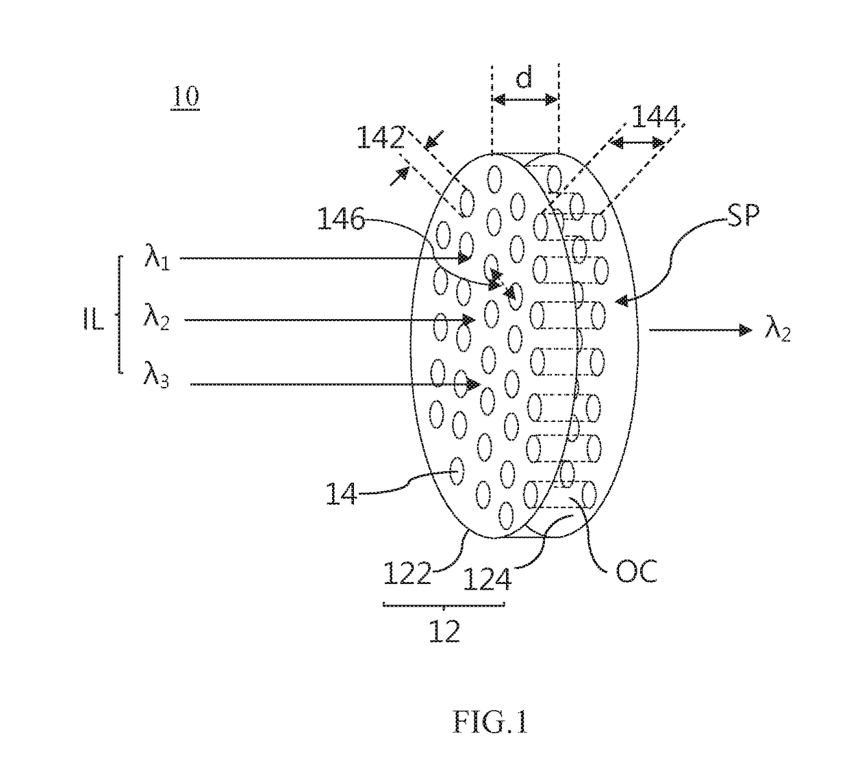
The present invention provides an anti-glare and light extinction optical lens that prevents harmful light from damaging user's eyes. The lens effectively filters harmful wavelengths by the microstructure without prejudice to the user's visual perception. The lens can also combine dyeing layer and polarizer layer to do multi optical processes to reduce and eliminate the damage of eyes by the harmful light. The lens has opening holes that stop harmful light, and an interference layer that selectively disposes the interference wavelength caused by the opening holes and the wavelength which is not disposed by the lens. The lens also increases the value of color or changes the polarization state for clearer image.

Problems solved by technology

A conventional optical lens although provides high optical transmittance, but the harmful light and harmless light unlimitedly enter the human's eyes.
The harmful light causes blurred vision and fuzziness vision, and furthermore damages the eyes, and even the retina for permanent damage.

Method used


Image

  • Anti-glare and light extinction optical lens
  • Anti-glare and light extinction optical lens
  • Anti-glare and light extinction optical lens

Examples


Embodiment Construction

[0022]In order to fully comprehend the objectives, features and efficacy of the present invention, a detailed description is described by the following substantial embodiments in conjunction with the accompanying drawings. The description is as below.

[0023]The description of unit, element and component in the present invention uses “one”, “a”, or “an”. The way mentioned above is for convenience, and for general meaning of the category of the present invention. Therefore, the description should be understood as “include one”, “at least one”, and include the singular and plural forms at the same time unless obvious meaning.

[0024]The description of comprise, have, include, contain, or another similar semantics has the non-exclusive meaning. For example, an element, structure, product, or device contain multi requirements are not limited in the list of the content, but include another inherent requirement of element, structure, product or device not explicitly listed in the content. In ...


PUM


Abstract

The present invention is an anti-glare and light extinction optical lens for adjusting an incident light to an emitting light, and the wavelength of the emitting light is part of the wavelength of the incident light, the anti-glare and light extinction optical lens comprises an optical carrier and a plurality of opening holes. The optical carrier has an incident surface and an emitting surface. An accommodation space is formed between the incident surface and the emitting surface. Wherein the incident surface is at a distance from the emitting surface. A plurality of opening holes is formed in the accommodation space of the optical carrier. The plurality of opening holes forms an optical tunnel, and each of the plurality of opening holes has a hole pitch from each other. Wherein when the incident light influxes from the incident surface into the accommodation space, the light tunnel filters out a part of wavelength of the incident light and outputs the emitting light from the emitting surface.

Description

FIELD OF THE INVENTION[0001]The present invention is related to the technical field of optical lens, particularly an anti-glare and light extinction optical lens formed by an optical structure.BACKGROUND OF THE INVENTION[0002]A conventional optical lens although provides high optical transmittance, but the harmful light and harmless light unlimitedly enter the human's eyes. The harmful light causes blurred vision and fuzziness vision, and furthermore damages the eyes, and even the retina for permanent damage.[0003]In light of the above, the present invention provides an anti-glare and light extinction optical lens to solve the conventional problem.SUMMARY OF THE INVENTION[0004]A first objective of the present invention is to provide an anti-glare and light extinction optical lens, forming a plurality of opening holes in the optical carrier, and the plurality of opening holes forms an optical tunnel to be the optical filter purpose.[0005]A second objective of the present invention is...

Claims


Application Information

Patent Timeline
Patent Type & Authority Applications(United States)
IPC IPC(8): G02C7/10G01J1/04G02B7/02
CPCG02C7/104G01J1/0407G02B7/02G02C7/108G02C7/10G02C7/12G02C7/16G02B5/0247G02C7/165
Inventor WU, NAI-MING
Owner HE SUNG GLASSES CO LTD
Learn More