
Projector with light pollution shield function and light pollution shielding method thereof

a technology of light pollution shielding and projector, which is applied in the direction of projectors, instruments, optics, etc., can solve the problems of projectors having a higher cost, user's eyes burning, and the process of focusing is quite bothersome for users,

Active Publication Date: 2017-05-30
QUISDA CORP
View PDF3 Cites 0 Cited by
  • Summary
  • Abstract
  • Description
  • Claims
  • Application Information

AI Technical Summary

Benefits of technology

The present invention is a projector that can prevent a user's eyes from being burned by the bright lights that come through the lens when switching between different lenses. This is done by using a sensor to detect when a lens is being disassembled and reducing or stopping the brightness of the projector. This feature is automatic and without the need for manual switching, making it more convenient and time-efficient. The invention also reduces production costs and the need for additional light shielding structures.

Problems solved by technology

However, turning off the backlight source for each switch of lens is quite bothering process and timing consuming for a user.
More seriously, if a user directly disassemblies a lens from the projector without turning off the backlight source in advance, the user may have his eyes burned.
However, the projector may have a higher cost due to that an additional light shielding structure is required.
Further, if an elastic structure (such as a spring) is used for the on / off switch of the movable light shielding structure, a user may still have his eyes burned once the elastic structure has elastic fatigue and cannot completely block the backlight source while switching the lenses.

Method used


Image

  • Projector with light pollution shield function and light pollution shielding method thereof
  • Projector with light pollution shield function and light pollution shielding method thereof
  • Projector with light pollution shield function and light pollution shielding method thereof

Examples


Embodiment Construction

[0020]The present invention will now be described more specifically with reference to the following embodiments. It is to be noted that the following descriptions of preferred embodiments of this invention are presented herein for purpose of illustration and description only. It is not intended to be exhaustive or to be limited to the precise form disclosed.

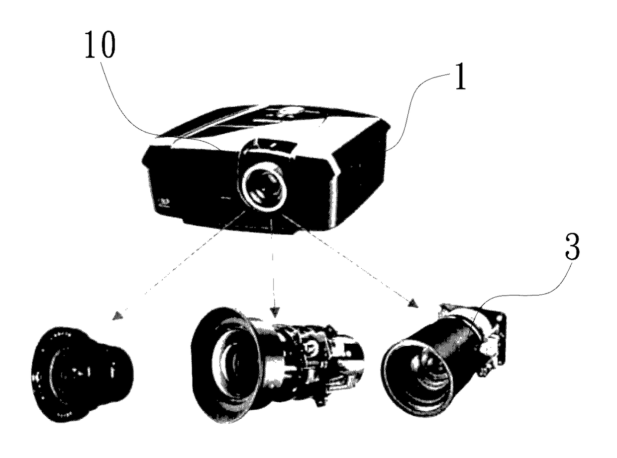
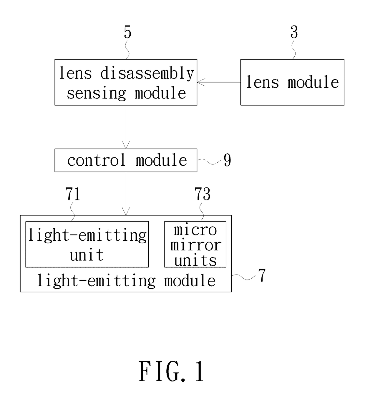
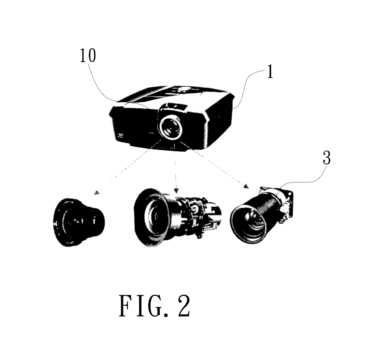
[0021]FIGS. 1 and 2 are block diagram and schematic view of a projector with a light pollution shielding function in accordance with an embodiment of the present invention. As shown in FIGS. 1 and 2, the projector of the present embodiment includes a projector body 1, a plurality of lens modules 3, a lens disassembly sensing module 5, a light-emitting module 7 and a control module 9. The projector body 1 has a light-permissive aperture 10. The plurality of lens modules 3 are individually provided for an assembly to the light-permissive aperture 10 of the projector body 1. The lens disassembly sensing module 5 is disposed in the p...


PUM


Abstract

A projector includes a projector body having a light-permissive aperture, a plurality of lens modules, a lens disassembly sensing module, a light-emitting module and a control module. The lens modules are individually provided for an assembly to the light-permissive aperture. The lens disassembly sensing module is disposed in the projector body and corresponding to the light-permissive aperture. The light-emitting module is disposed in the projector body and configured to emit lights toward the light-permissive aperture. The control module is signally connected to the lens disassembly sensing module and the light-emitting module. The control module is configured to sense, through the lens disassembly sensing module, whether any one of lens modules is being disassembled from the light-permissive aperture and modulate a lighting intensity of the light-emitting module when a lens module being disassembled from the light-permissive aperture is sensed. A light pollution shielding method for the projector is also provided.

Description

FIELD OF THE INVENTION[0001]The present invention relates to a projector with light pollution shielding function and a light pollution shielding method thereof, and more particularly to a projector with light pollution shielding function and a light pollution shielding method thereof capable of preventing a backlight source from continually emitting lights while a lens module is being disassembled from the projector.BACKGROUND OF THE INVENTION[0002]Currently, the high-end projectors on the market are implemented with multiple lens switchable function, so that a user can purchase one projector only and assembly a particular lens (such as a telephoto lens or short focus lens) into the projector based on the corresponding environment.[0003]In generally, backlight source of high-end projector on the market has a relatively-high illumination; therefore, a user may have his eyes burned by the light with relatively-high illumination when the user directly eyes the projector while switching...

Claims


Application Information

Patent Timeline
IPC IPC(8): G03B21/20G03B21/14
CPCG03B21/2053G03B21/142G03B21/2066G03B21/145
Inventor CHANG, WEI-CHUNLIN, YING-FANG
Owner QUISDA CORP
Learn More