
Universal performance monitor for power generators

a technology for power generators and monitors, applied in the field of universal performance monitors for power generators, can solve the problems of difficult to collect and integrate data from these applications and systems outside of the intended operation, and inability to meet the requirements of the intended operation

Inactive Publication Date: 2015-12-31
VERSIFY SOLUTIONS
View PDF4 Cites 19 Cited by
  • Summary
  • Abstract
  • Description
  • Claims
  • Application Information

AI Technical Summary

Benefits of technology

This solution provides a flexible and efficient means to monitor and report power generation operations, integrating disparate data sources and reducing the need for custom code, thereby improving data accessibility and operational efficiency.

Problems solved by technology

However, these applications are typically not built with integration in mind with each application being too proprietary in nature and specifically tailored for a particular power generation operation.
Accordingly, collection and integration of data from these applications and systems are extremely difficult outside of the intended operation.
Many utilities have sought to create a large scale data warehouse to solve this integration problem with very little success.
Another difficulty with prior art systems is the disparate number of locations even within the organization that needs access to the data.
The traditional siloed applications are typically client-server based applications and it is difficult to provide access to everyone in need of the data.
In addition, due to the generally isolated nature of the prior art systems as described above, combining qualitative event type data (e.g., real-time or recorded plant operations data) and quantitative data (e.g., Supervisory Control and Data Acquisition (SCADA) and market data) becomes difficult and cumbersome, if not impossible, due to the size and disparity of the data.
This task becomes even more complicated when disparate data sources with varying data formats are used.

Method used


Image

  • Universal performance monitor for power generators
  • Universal performance monitor for power generators
  • Universal performance monitor for power generators

Examples


Embodiment Construction

General Description

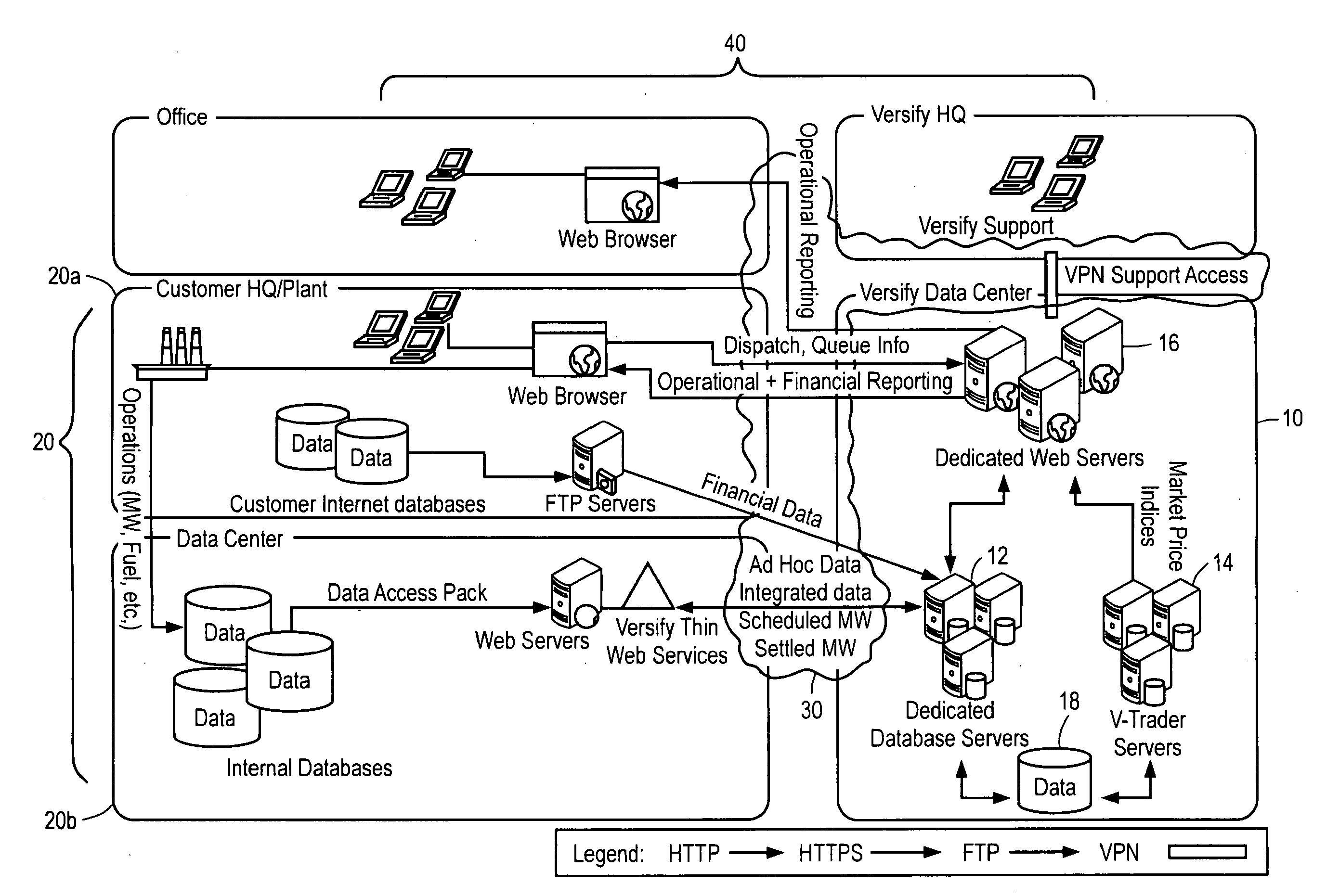
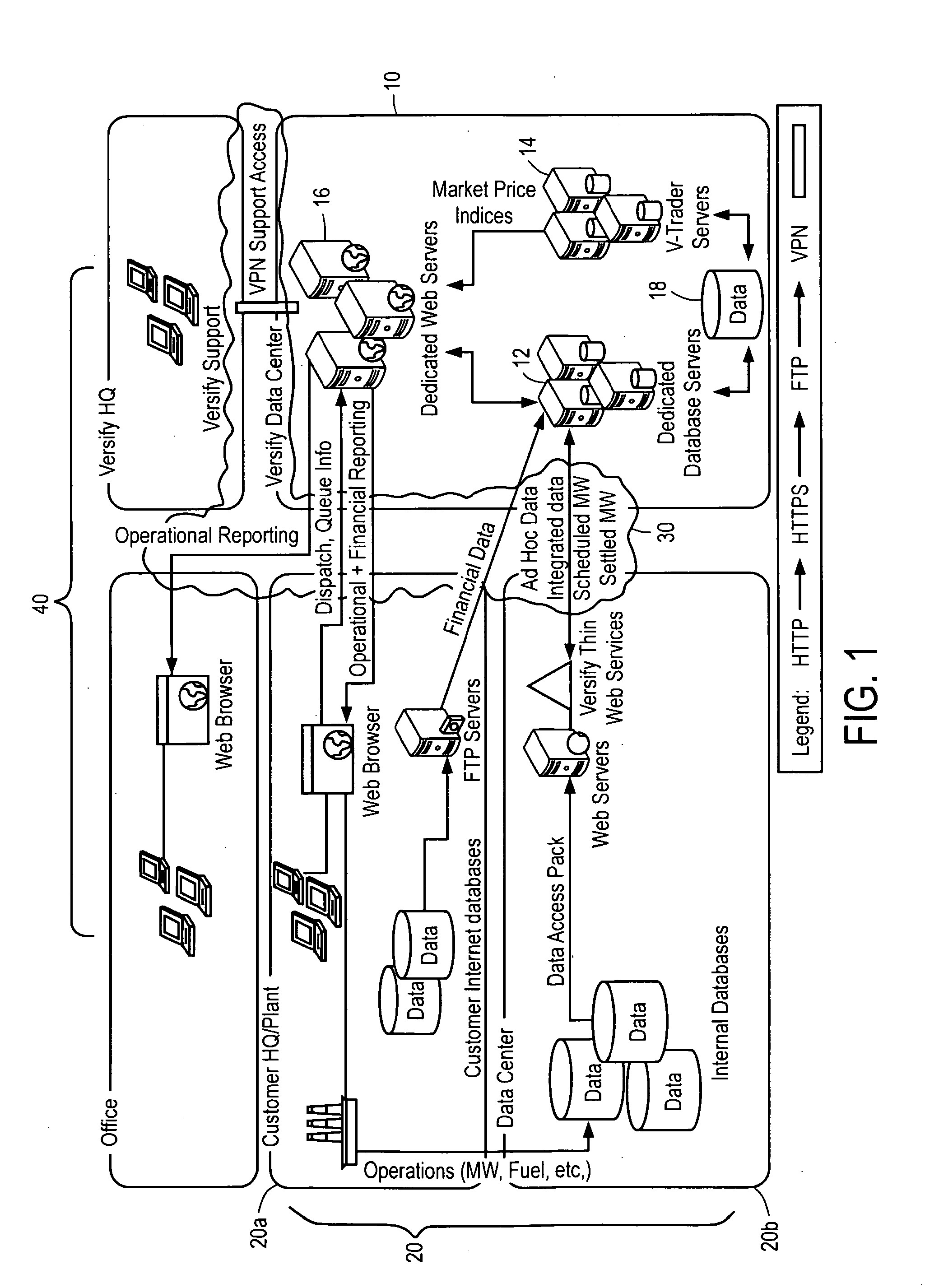
[0025]The invention generally encompasses systems including:

[0026]a communications network;

[0027]a plurality of remotely located data sources to provide power data, the power data including quantitative and qualitative data of one or more power generation units; and

[0028]a performance monitor in communication with the plurality of remotely located data sources through the communications network, the performance monitor including

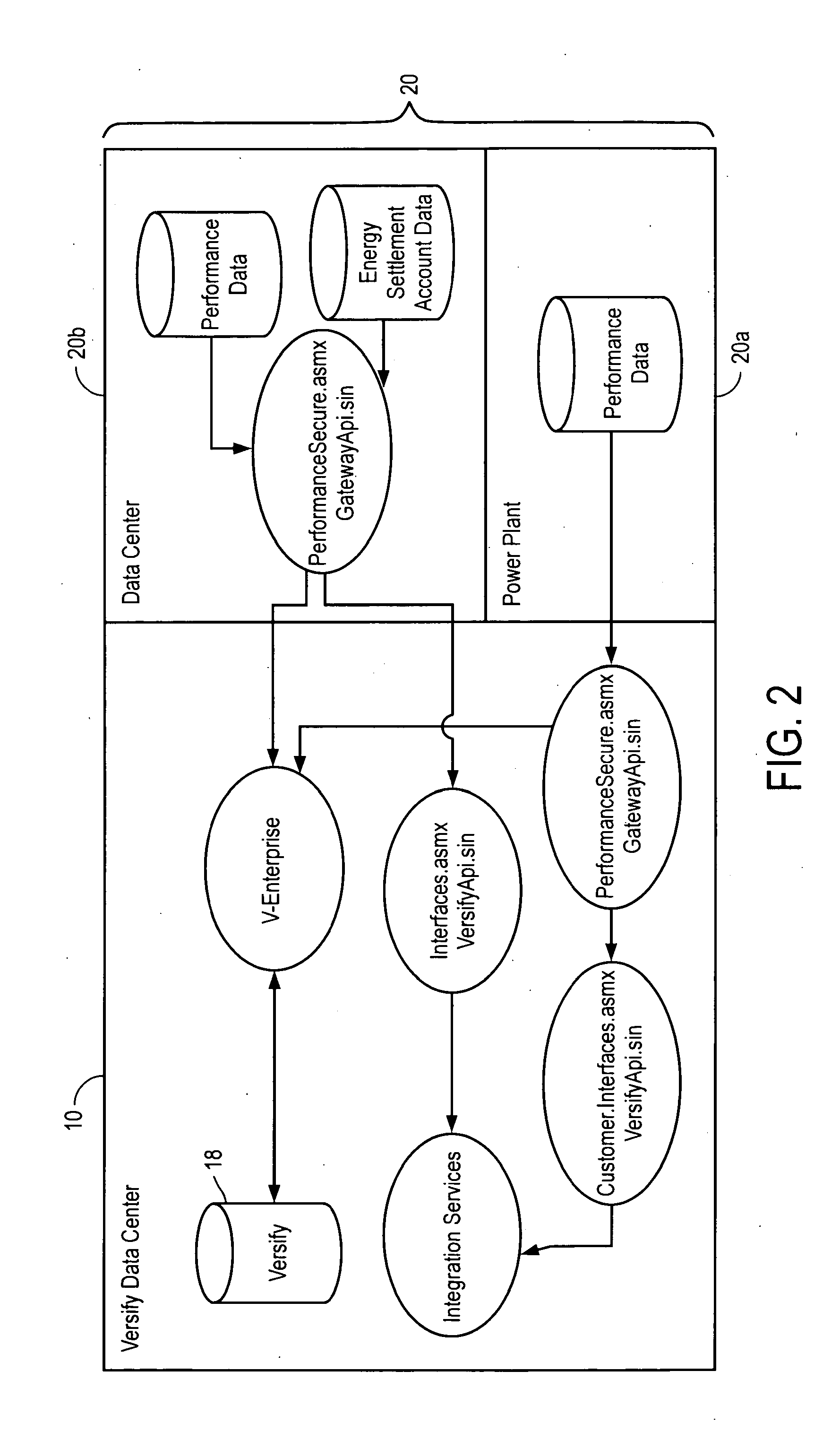
[0029]a communications unit to extract the power data from the plurality of remotely located data sources,

[0030]a data conversion unit to transform the power data into a common data format,

[0031]a data store to store the transformed power data, and

[0032]a user interface unit to display the transformed power data on one or more client devices through the communications network.

[0033]In certain illustrative embodiments, the quantitative data includes supervisory control and data acquisition (SCADA) data and / or market data.

[0034]In certain ill...


PUM


Abstract

The invention broadly encompasses a system including a communications network, a plurality of remotely located data sources to provide power data, the power data including quantitative and qualitative data of one or more power generation units, and a performance monitor in communication with the plurality of remotely located data sources through the communications network, the performance monitor including a communications unit to extract the power data from the plurality of remotely located data sources, a data conversion unit to transform the power data into a common data format, a data store to store the transformed power data, and a user interface unit to display the transformed power data on one or more client devices through the communications network.

Description

[0001]This application is a continuation application of copending U.S. application Ser. No. 12 / 399,689, filed on Mar. 6, 2009, which claims the benefit of U.S. provisional patent application No. 61 / 034,912, which was filed on Mar. 7, 2008, both of which are hereby incorporated by reference in their entirety.I. FIELD OF THE INVENTION[0002]The invention encompasses a performance monitor for power generators, and more particularly to a performance monitor for power generators that is adaptable to handle data from any data source.II. BACKGROUND OF THE INVENTION[0003]The power industry has been rapidly changing with the advent of deregulation as well as other socio-economic factors. As a result, increases in efficiency and control of power generation costs are becoming of more importance. To meet the industry needs, a large number of siloed information technology (IT) applications have been introduced. However, these applications are typically not built with integration in mind with each...

Claims


Application Information

Patent Timeline
Patent Type & Authority Applications(United States)
IPC IPC(8): G06F1/32G06F13/14
CPCG06F3/05H02J13/001G06F1/3209G06F13/14Y04S10/40H02J13/00001
Inventor IPPOLITO, DAVIDKUCHARCZUK, DAVID
Owner VERSIFY SOLUTIONS
Learn More