Permanent magnet machine

Active Publication Date: 2015-12-31
GENERAL ELECTRIC CO
View PDF20 Cites 54 Cited by
  • Summary
  • Abstract
  • Description
  • Claims
  • Application Information

AI Technical Summary

Problems solved by technology

The bridges of posts with increased thickness lead to higher magnet flux leakage, which significantly reduces the machine power density, resulting in decreased efficiency of the machine.
The speed at which the rotor can turn safely is limited by centrifugal loading on the permanent magnets and

Method used


Image

  • Permanent magnet machine
  • Permanent magnet machine
  • Permanent magnet machine

Examples


Embodiment Construction

[0020]The disclosure will be described for the purposes of illustration only in connection with certain embodiments; however, it is to be understood that other objects and advantages of the present disclosure will be made apparent by the following description of the drawings according to the disclosure. While preferred embodiments are disclosed, they are not intended to be limiting. Rather, the general principles set forth herein are considered to be merely illustrative of the scope of the present disclosure and it is to be further understood that numerous changes may be made without straying from the scope of the present disclosure.

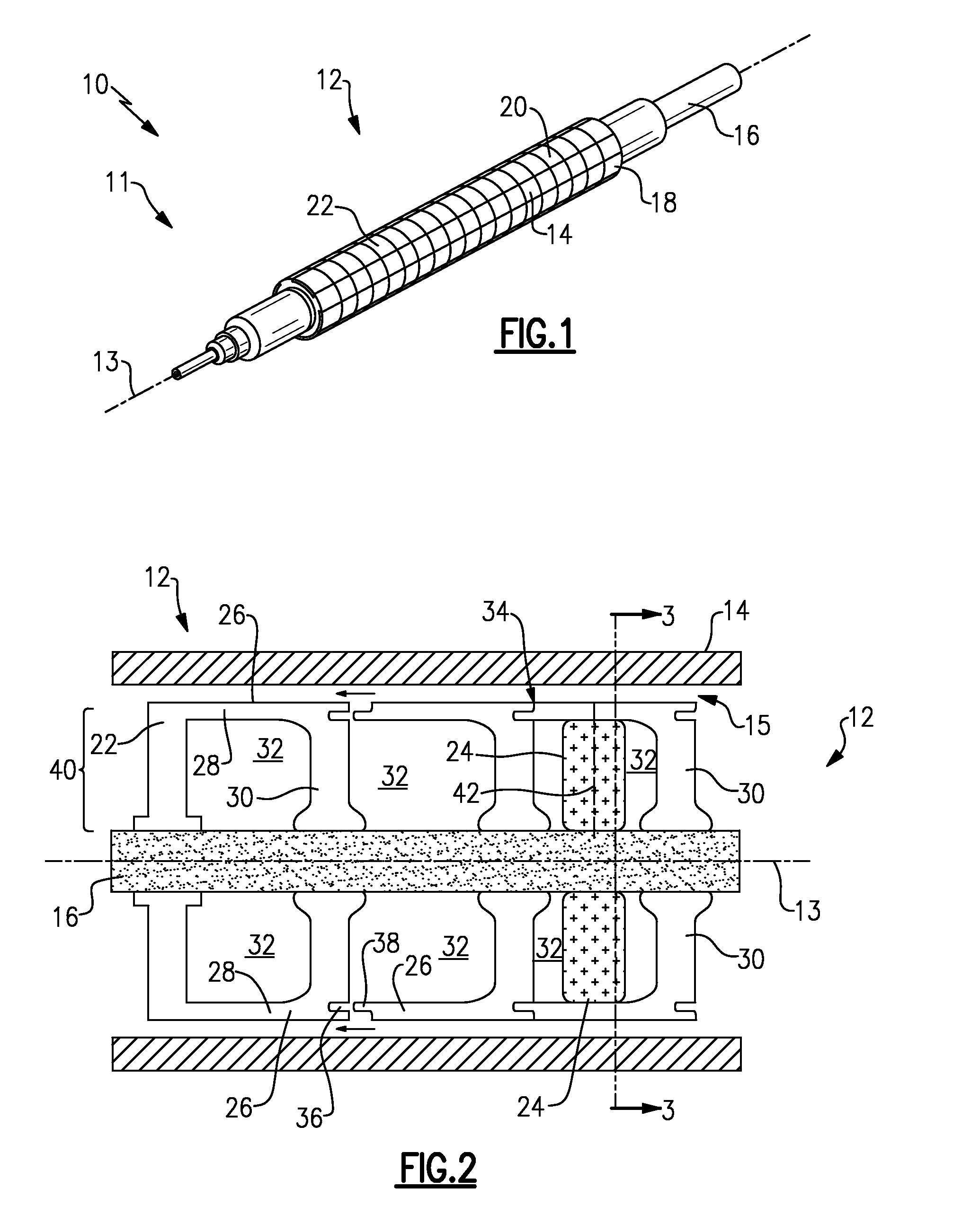
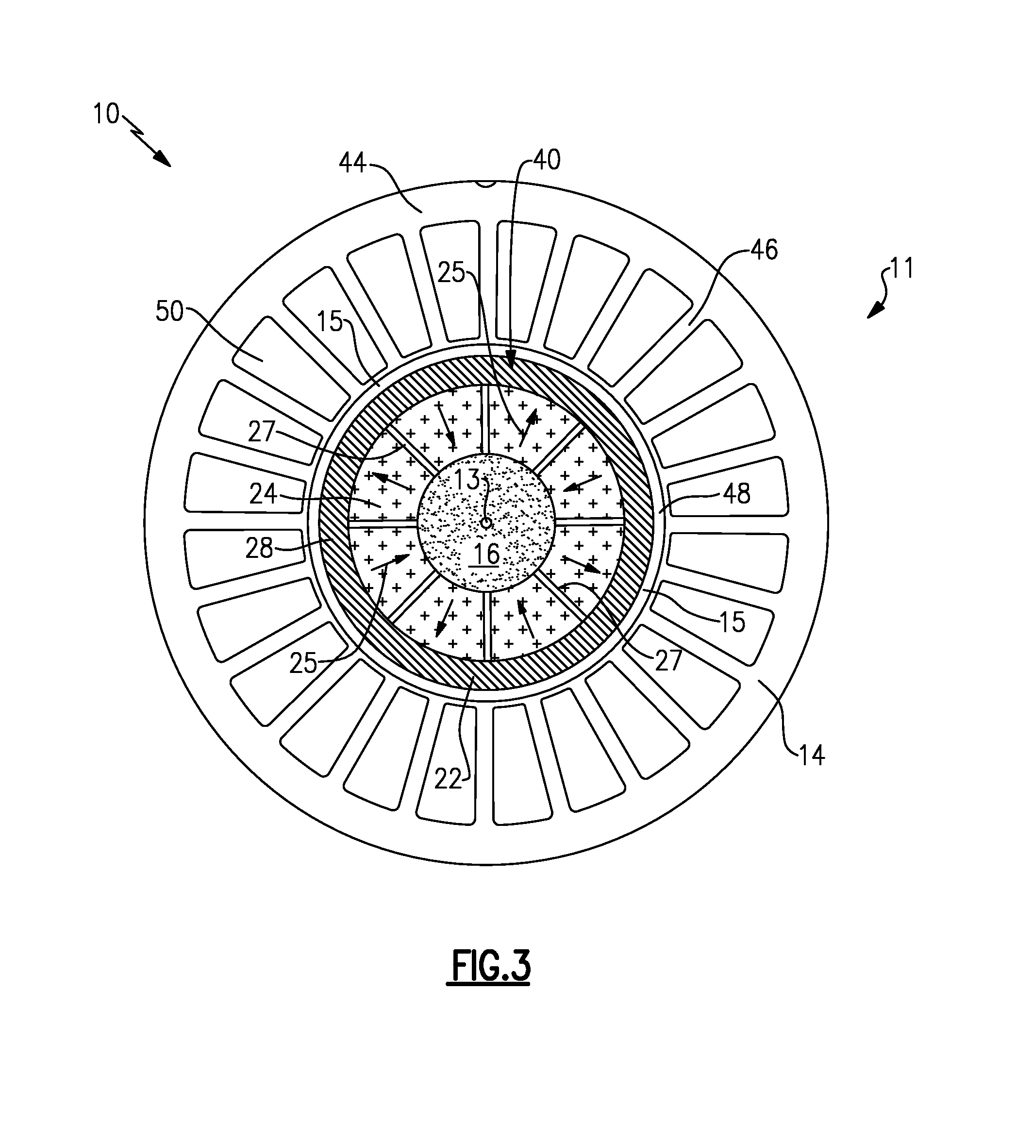
[0021]As described in detail below, embodiments of the present disclosure provide a permanent magnet machine including a sleeve component having an increased centrifugal load capacity in light of reduced overall weight, so as to provide increased power density and improved electrical performance. Using such disclosed configurations, the permanent magnet ...


PUM


Abstract

A permanent magnet machine and a rotor assembly for the permanent magnet machine. The permanent magnet machine includes a stator assembly including a stator core configured to generate a magnetic field and extending along a longitudinal axis with an inner surface defining a cavity and a rotor assembly including a rotor core and a rotor shaft. The rotor core is disposed inside the stator cavity and configured to rotate about the longitudinal axis. The rotor assembly further including a plurality of permanent magnets for generating a magnetic field which interacts with the stator magnetic field to produce torque. The permanent magnets are disposed within one or more cavities formed in a sleeve component. The sleeve component configured to include a plurality of cavities or voids therein and thus provide minimal weight to the permanent magnet machine. The permanent magnet machine providing increased centrifugal load capacity, increased power density and improved electrical performance.

Description

BACKGROUND[0001]The present disclosure relates to permanent magnet machines. More particularly, the present disclosure relates to a high-speed permanent magnet motor machine with high power density.[0002]Interior Permanent Magnet Machines (IPMs) such as permanent magnet motors or generators have been widely used in a variety of applications including aircraft, automobile, subsea and industrial usage. A requirement for lightweight and high power density permanent magnet machines has resulted in the design of higher speed motors and generators to maximize the power to weight ratios. Hence, the trend is increasing acceptance of permanent magnet machines offering high machine speed, high power density, reduced mass and cost.[0003]Permanent magnet motors typically employ permanent magnets either in the rotor, the stator or both. In most instances, the permanent magnets are found within the rotor assembly. The output power of the permanent magnet motor is determined by the length, diamete...

Claims


Application Information

Patent Timeline
IPC IPC(8): H02K1/28H02K7/14H02K1/27
CPCH02K1/28H02K1/278Y02E10/725H02K21/026H02K1/30H02K21/24H02K49/108H02K1/182Y02E10/72
Inventor JOSHI, NARENDRA DIGAMBERSHAH, MANOJ RAMPRASADBRAY, JAMES WILLIAMVONDRELL, RANDY MARINUSMURROW, KURT DAVIDHAMEL, JEFFREY ANTHONYMARTIN, SAMUEL JACOB
Owner GENERAL ELECTRIC CO
Why Eureka
Try Eureka