

Relay system for transmitting IP address of client to server and method therefor
- Summary
- Abstract
- Description
- Claims
- Application Information
AI Technical Summary
Benefits of technology
Problems solved by technology
Method used
Image

Examples
first embodiment
[0034]FIG. 3B illustrates a structure of a packet when a relay system operates in the forward transmission mode according to the inventive concept.
second embodiment
[0035]FIG. 3C illustrates a structure of a packet when a relay system operates in the forward transmission mode according to the inventive concept.
[0036]FIG. 4A illustrates a structure of a packet when a relay system operates in the backward transmission mode according to a first embodiment of the inventive concept.
[0037]FIG. 4B illustrates a structure of a packet when a relay system operates in the backward transmission mode according to a second embodiment of the inventive concept.
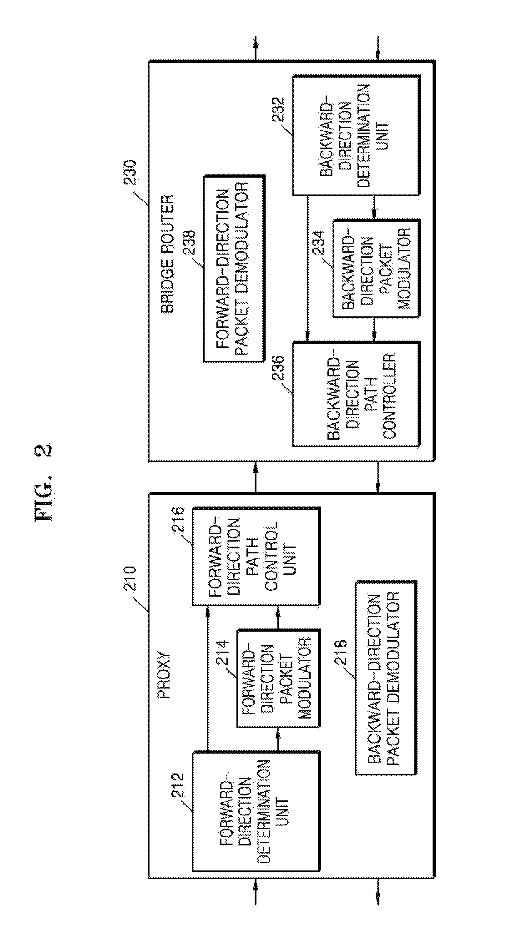
[0038]FIG. 5 is a block diagram of a proxy included in a relay system according to an embodiment of the inventive concept.
[0039]FIG. 6 is a block diagram of a bridge router included in a relay system according to an embodiment of the inventive concept.
[0040]FIG. 7A to 7E are block diagrams of relay systems according to various embodiments of the inventive concept.
[0041]FIG. 8 illustrates a network structure in which a first client transmits a packet to a first server or a second server via a relay system...
PUM
 Abstract
Description
Claims
Application Information