Delay mechanism suitable for compact automatic injection device

a delay mechanism and compact technology, applied in the direction of injection needles, intravenous devices, automatic syringes, etc., can solve the problems of less reliable means for holding the needle in a retracted position after use, the delay mechanism is not as compact axially, and the device is longer. , to achieve the effect of compact design

Active Publication Date: 2016-01-07
ELI LILLY & CO
View PDF4 Cites 11 Cited by
  • Summary
  • Abstract
  • Description
  • Claims
  • Application Information

AI Technical Summary

Benefits of technology

[0008]One advantage of the present invention is that a delay mechanism may be provided which is compact in design.
[0009]Another advantage of the present i

Problems solved by technology

One problem with at least some automatic injection devices having delay mechanisms is that the devices are longer than some users may like when placed by the user on an injection site.
However, as causing such syringes to inject tends to require the application of more force and therefore a more robust drive system, constraints can result as to where the delay mechanism can be accommodated within the device housing.
Still further, some delay mechanisms are not as compact axially

Method used


Image

  • Delay mechanism suitable for compact automatic injection device
  • Delay mechanism suitable for compact automatic injection device
  • Delay mechanism suitable for compact automatic injection device

Examples


Embodiment Construction

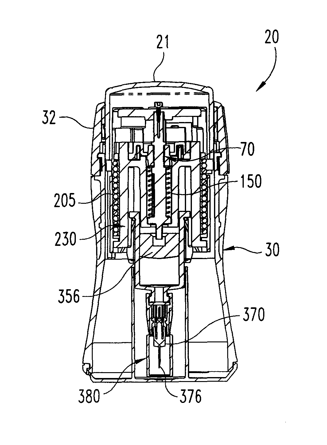
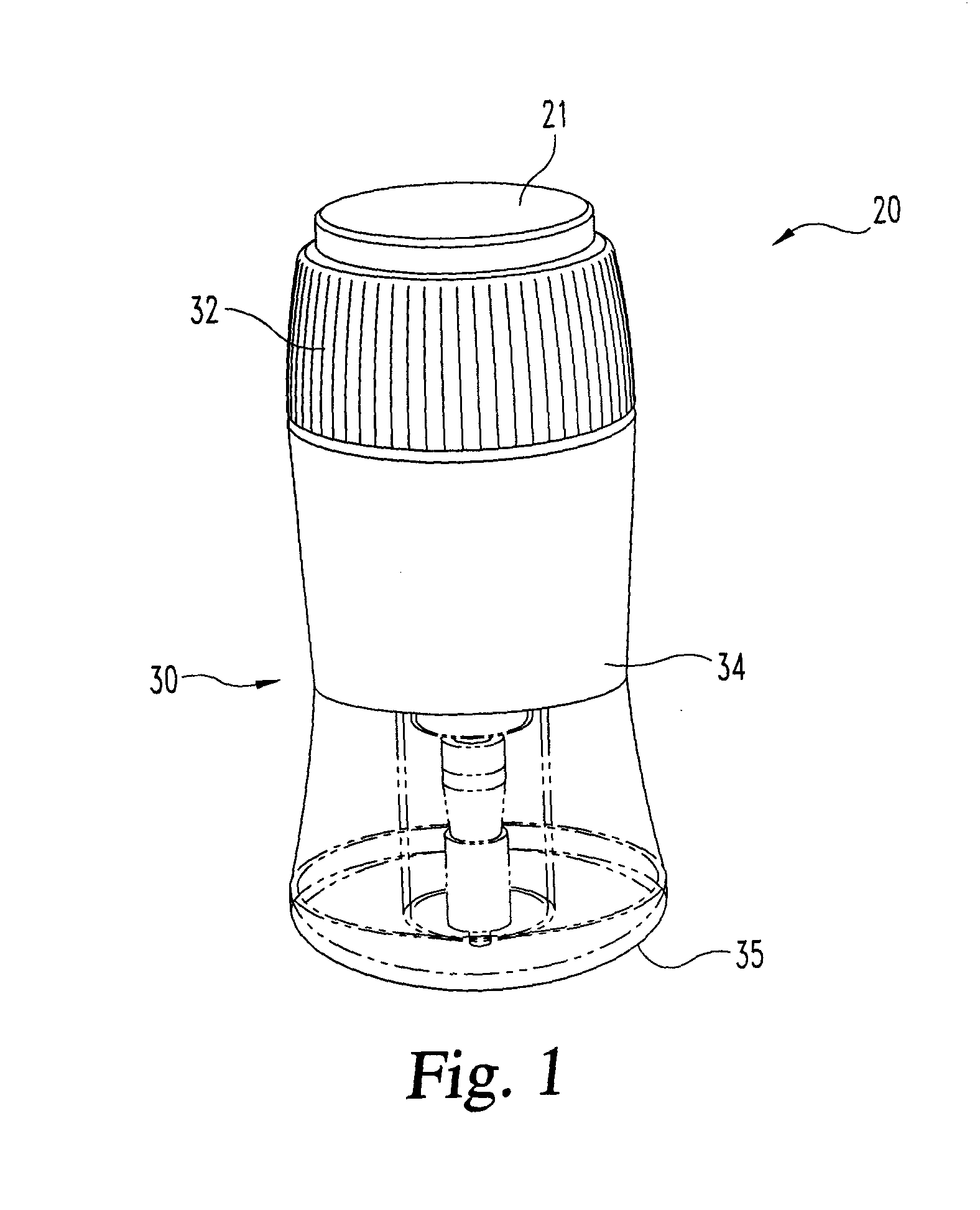
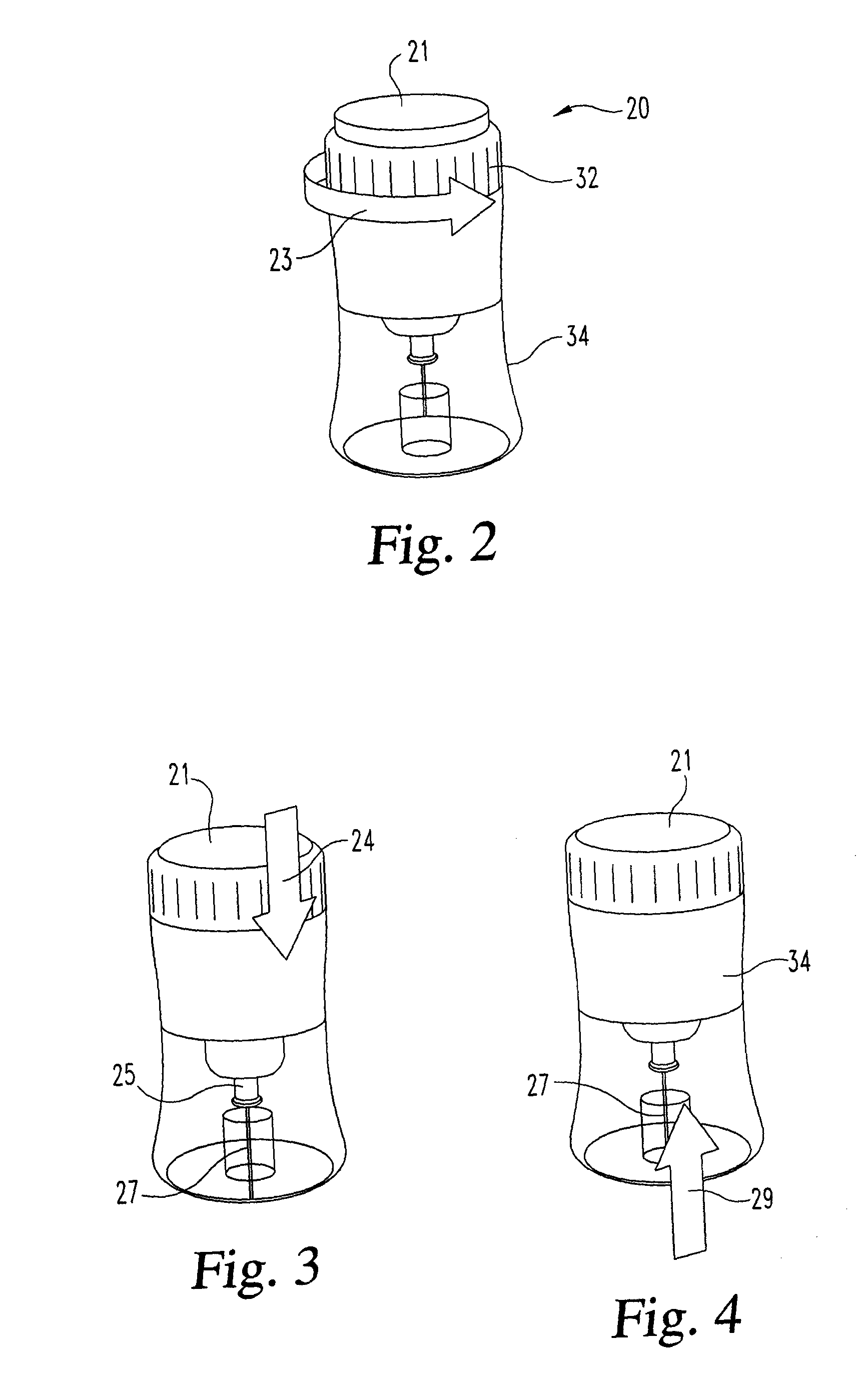
[0029]In FIG. 1, there is shown a perspective view of a first embodiment of an automatic injection device, generally designated 20, with a delay mechanism of the present invention. In FIGS. 2-4, device 20 is shown abstractly with a simple needled syringe, and with its needle cover, which during use is collapsed and pierced during an injection, not being shown. In FIG. 2, device 20 is shown being unlocked by rotating the safety sleeve 32 as indicated by arrow 23 about the housing main body 34 to an unlocked angular position. After device unlocking, and when the trigger button 21 is depressed as indicated by arrow 24, the needled syringe 25 of the device 20 is automatically driven downward such that the injection needle 27 of syringe 25 projects beyond the bottom end of the device housing to penetrate the user as shown in FIG. 3. The device then proceeds to inject automatically, that is without further user action, the medication contents of the syringe 25 through the needle 27, after...


PUM


Abstract

A delay mechanism for an automatic injection device having a housing and a medication filled syringe. The delay mechanism includes a shuttle, a follower, a damping compound, at least one biasing member, and a biased plunger element. When moved in the device housing from a first location to a second location, the biased plunger element is adapted to drive the syringe piston within syringe barrel to force medication through the syringe needle for an injection. The follower, when the plunger element is so moved, is freed to move, under urging of the at least one biasing member, from a first position on the housing toward a second position to thereby move the shuttle for retracting the syringe needle into the housing after injection. The damping compound dampens or slows rotation of the follower as the follower moves from the first position toward the second position.

Description

BACKGROUND OF THE INVENTION[0001]The present invention pertains to pharmaceutical injection devices, and, in particular, to a mechanism used to delay needle retraction for an automatic injection device.[0002]Patients suffering from a number of different diseases frequently must inject themselves with pharmaceuticals. A variety of devices have been proposed to facilitate these injections. One type of device is an automatic injection device. This type of device, when triggered by a user or someone helping the user, automatically inserts into the user a needle of a syringe that prior to triggering was disposed within the device housing, and then automatically injects a dose of medication through that inserted needle. One known type of automatic injection device then automatically advances a shroud to cover the needle when the dose is completed. In another type of automatic injection device having a configuration more desirable to some, and instead of having an advancing shroud, the dev...

Claims


Application Information

Patent Timeline
IPC IPC(8): A61M5/20A61M5/32
CPCA61M5/3234A61M5/2033A61M5/326A61M2005/206
Inventor FOURT, JESSE ARNOLDSIMPSON, BRADLEY JAMES
Owner ELI LILLY & CO
Why Eureka
Try Eureka